
Tape recorder interface

The described circuit utilizes a series of integrated circuits (ICs) to facilitate the encoding and decoding of data for storage on magnetic tape. The XOR gate (IC 1/1) is essential for modulating the data stream with the clock signal, ensuring that the recorded signals maintain synchronization with the timing reference. The amplitude adjustment before sending the signal to the tape recorder is crucial, as it prevents distortion and ensures reliable playback.
During playback, the CMOS gate (IC 1/2) amplifies the incoming pulses to a level suitable for further processing. The linear amplifier configuration allows for a faithful reproduction of the recorded data, ensuring that the TTL signal levels are achieved for subsequent digital processing.
The use of IC 1/4 to create short pulses upon detecting transitions in the signal is an effective method for capturing the rapid changes in the data stream. This functionality is critical for accurately representing the original data, especially in sequences of identical bits, where the one-shot timer (IC 2) must be retriggered to avoid missing transitions.
The D-type flip-flop (IC 3) serves as a memory element, capturing the state of the data stream at precise moments dictated by the pulse widths generated by IC 2. This allows for the reconstruction of the original data sequence at the output, which can then be processed by the Z80 DUART. The configuration of the DUART to operate at 38.4 kHz, which is 16 times the data rate, ensures that the data can be reliably received and processed without errors, facilitating efficient communication in digital systems. Overall, this circuit design showcases a practical approach to data storage and retrieval using analog media, leveraging digital logic components to achieve reliable performance.The interface allows data to be saved on an ordinary tape recorder at a speed of 2400 bit/s. The serial stream of data Fig. 1 (A) is coded with a clock of 2400 Hz (B), by means of XOR gate IC 1/1. Logical "high" and "low" appear as shown in Fig. 2 (C). These impulses are lowered in amplitude and feed into the record input of a low cost tape recorder. During the playback, pulses (D) are amplified with CMOS gate IC 1/2 connected as a linear amplifier, and providing a TTL level signal shown in (E). On both positive and negative transitions IC 1/4 forms short pulses as shown in (F) (approx. 50 *ts) that triggers one shot IC2. A monostable one shot pulse width is adjusted to be 3A of bit length (310 µß). A change from "high" to "low" in a coded stream generates a "low" pulse width of one bit cell. The same is for change from ' low'' to ' 'high'' that generates a "high" pulse of the same width. During this pulse one shot latches the state of line in D type flip-flop IC3 (G). When a stream consists of multiple "ones" or "zeros," the one shot is retriggered before it comes to the end of the quasistable state and the state of the flip-flop remains unchanged. The original data stream is available at the output of the flip-flop (). Z80 the DUART that receives these pulses is programmed so that the receiver clock is 16 times the data rate (38.4 kHz).
Related Circuits
Unlike most surface-mounted device (SMD) resistors, SMD ceramic capacitors do not have their values marked. To determine the value of these capacitors, a capacitance meter is required. SMD ceramic capacitors are widely used in modern electronic circuits due to their...
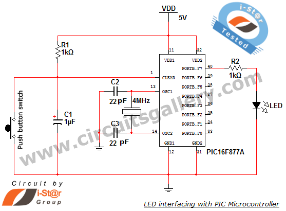
How to interface an LED with Microchip's PIC microcontroller. Connecting LEDs to a PIC microcontroller is fundamental for microcontroller development. This guide presents a simple embedded program for the PIC 16F877A to interface LEDs, making it suitable for beginners...
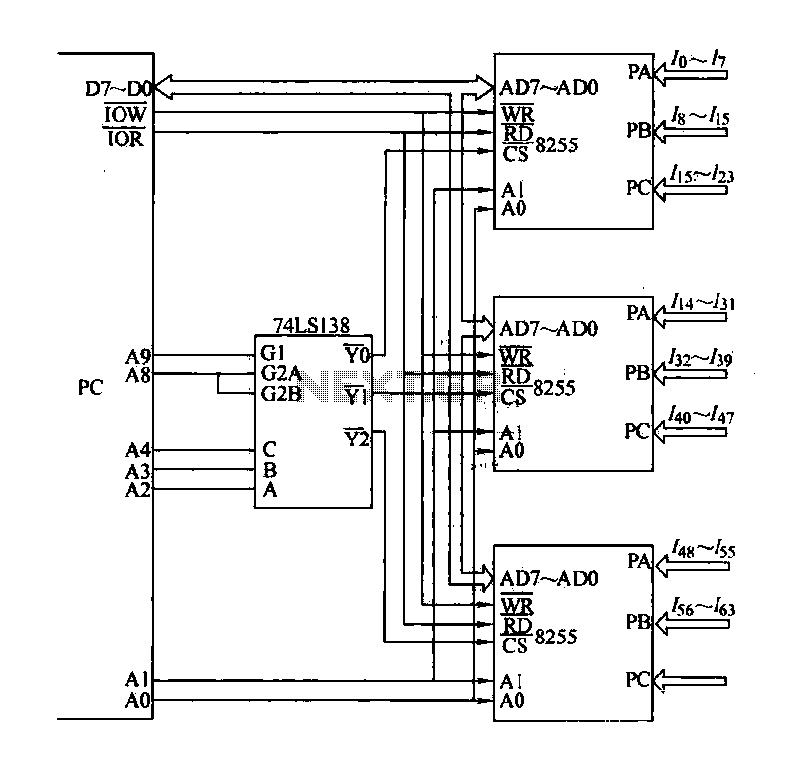
The computer control system is designed to detect signal path switching, requiring multiple input interface expansions. This system can switch all signal inputs into the computer. By utilizing a programmable chip, the 8255 expansion input interface allows for three...
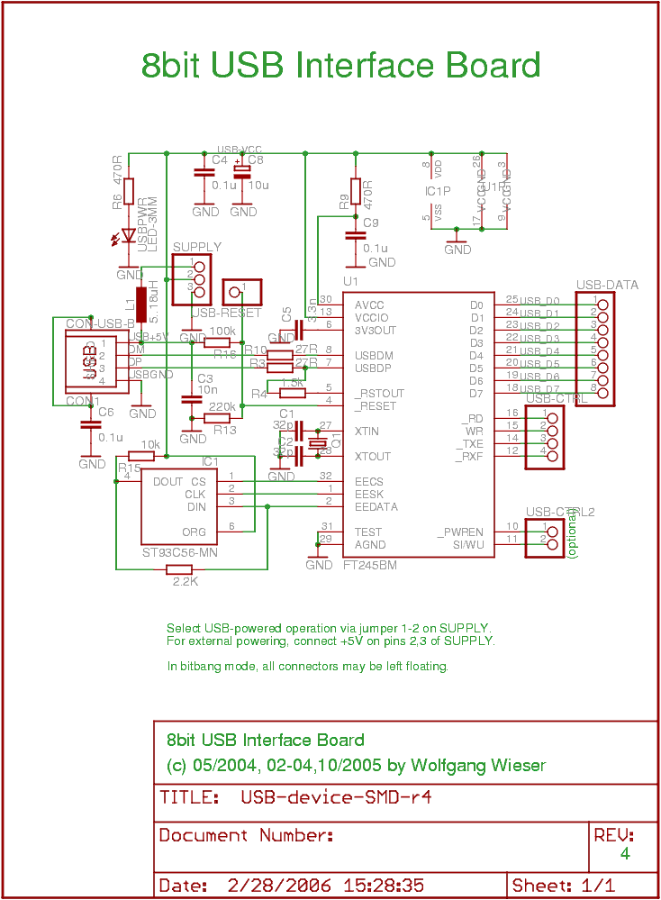
The objective was to create a compact USB interface board that can be easily connected to microcontroller boards. It is designed to support both USB-powered and externally-powered operation. The number of external components has been minimized, although there are...
This design is based on the work of Andrew Bruno, referred to as "bruno-if." The contribution involved providing Postscript files for a Printed Circuit Board. The circuit is relatively old, dating back to the NMEA-0180 and NMEA-0182 standards. It...
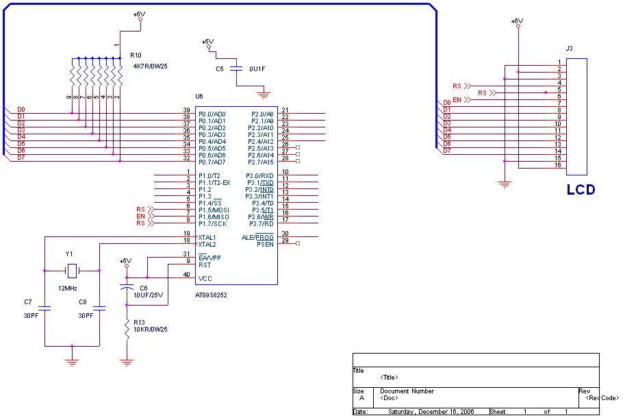
How to interface an LCD to the 89C51 microcontroller using 4-bit mode. A Lampex 16200 controller is being used; please send the manual for this controller. To interface an LCD with the 89C51 microcontroller using 4-bit mode, the following steps...