
Tarry light

The circuit described functions as a time delay switch for controlling a light. The operation begins when the user presses the push-button switch (SW2). This action charges capacitor C1 through diode D5, allowing it to accumulate the full DC voltage provided by the diode bridge. The time delay is adjustable via the potentiometer R4, which, in conjunction with resistors R2 and R3, forms a voltage divider that dictates the discharge rate of capacitor C1 once the push button is released.
As the capacitor discharges through the resistive network, the voltage across it decreases gradually. Diode D6 serves a crucial role by sampling this decaying voltage and directing it to the gate terminal of the silicon-controlled rectifier (SCR) Q1. The SCR is a semiconductor device that, once triggered into conduction by sufficient gate voltage, will continue to conduct until the voltage at its gate falls below a certain threshold, known as the holding voltage.
The time delay for the light to remain on is determined by the values of R2, R3, and R4, which collectively control the discharge time of capacitor C1. This allows for a range of delay settings from a few seconds to just under three minutes, making the circuit versatile for different applications. When the voltage at the gate of Q1 drops below the holding voltage, the SCR turns off, cutting power to the light and completing the cycle. This design effectively utilizes basic electronic components to achieve a reliable timing function for lighting applications.The push button and potentiometer initiate a time delay that turns a light on then automatically turns it off again after a predetermined time. The potentiometer can be set for a delay of a few seconds to just under three minutes. When the push-button switch SW2 is pressed, capacitor Cl gets charged through D5 to the full dc voltage developed by the diode bridge.
When the button is released, the charged capacitor is connected across the series combination of R2, R3, and potentiometer R4 whose setting determines the total-resistance and thereby sets the time it takes for the capacitor to discharge A steering diode, D6, connected to the j unction of R2 and R3, and potentiometer R4 whose setting determines The total resistance and thereby sets the time it takes for the capacitor to discharge. Diode, D6 picks off a portion of this decaying dc voltage and applies it to the gates terminal of Ql, the SCR, triggering it into a conductive state.
This SCR will remain on as long as there is sufficient voltage on its gate. As soon as this voltage decays below the minimum holding voltage of the SCR, it will turn off on the next line alternation.
Related Circuits
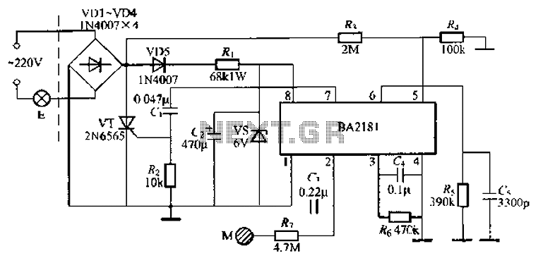
The BA2181 is a dimming controller that utilizes ASIC technology for touch-based stepping dimming of lights. It operates with low power consumption and has strong anti-interference capabilities. The device is compact and stable, making it suitable for various applications....
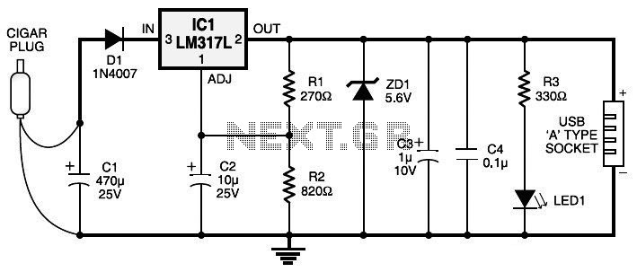
Currently, nearly all computer systems include logic blocks designed for interfacing with a USB port. In practical terms, a USB port can provide more than 100 mA of continuous electric current at 5V to the peripherals connected to the...
This article discusses the design of an LED driver for automotive rear lights. It demonstrates that dimming is most effectively accomplished using pulse-width modulation (PWM) in conjunction with an LED driver integrated circuit (IC) that removes the requirement for...
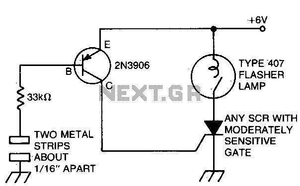
The battery-powered light activates with ease, remaining illuminated for a few seconds before automatically shutting off. The circuit is engaged when a finger bridges the gap between two metal strips, approximately 1/16 inch apart. Sufficient current flows through the...
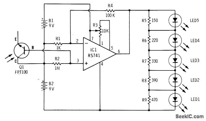
The phototransistor Q1 (Radio Shack 276-130) activates a voltage change across resistor R2, which is then amplified by an operational amplifier (op-amp). The output from the op-amp drives an array of five LEDs, creating a bar graph voltage indicator....
Any type of flashing light on the main brake lights is prohibited and illegal in most states of the U.S.A. Verification is being conducted for the same in Canada. Meanwhile, using this circuit is at one's own risk, with...