
task 32 triple axis accelerometer

The circuit diagram depicts the integration of an accelerometer with an Arduino microcontroller, providing a clear representation of how these components interact within an electronic system. The accelerometer, a device that measures acceleration forces, is connected to the Arduino board, which serves as the central processing unit for data collection and processing.
In this setup, the accelerometer typically has three output pins corresponding to the X, Y, and Z axes of acceleration. These pins are connected to the analog input pins of the Arduino board, allowing the microcontroller to read the acceleration data. The external power source is essential for powering both the accelerometer and the Arduino, ensuring that the circuit operates efficiently.
The power connections are usually made by connecting the VCC pin of the accelerometer to the positive terminal of the external power source, while the GND pin is connected to the ground. This configuration ensures that the accelerometer receives the necessary voltage for proper operation.
In addition to the basic connections, pull-up or pull-down resistors may be included in the schematic to stabilize the signal levels and prevent floating inputs. Capacitors can also be integrated into the circuit to filter out noise and provide a stable power supply to the components.
Overall, this circuit diagram serves as a fundamental illustration for those looking to utilize an accelerometer with an Arduino platform, facilitating various applications such as motion detection, tilt sensing, and gesture recognition.a circuit diagram showing how the accelerometer is connected to an Arduino board & external power source (not complicated at all, is it) 🔗 External reference
Related Circuits
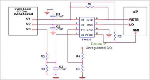
Introduction The SP6648 integrated synchronous boost regulator is a compact circuit that provides ultra-high efficiency drive current for an LED flashlight using a Luxeon I light source. The circuit is configured to deliver a constant output current of 350mA...
It is entirely logical that low-cost miniature microcontrollers have fewer pins than their larger counterparts, sometimes too few. Consideration has been given to how to economize on pins by making them perform the work of several. It was noted...

A hybrid amplifier is being developed, utilizing an Aikido configuration for the voltage amplification stage (VAS) and an emitter-follower variation for the output stage (OPS). The hybrid amplifier design integrates two distinct amplification stages to achieve high performance and...
The circuit is drawn for measurement of acceleration from 1000 mg until + 1000 mg. It can be placed in the car and be supplied from the sheath of the electric lighter. The circuit includes one indicative LED and...
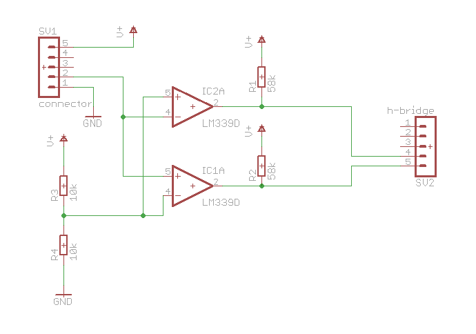
Here is a simple schematic of one of the components. The concept is that if the probed voltage is below half of the reference voltage, one LED will illuminate; otherwise, the second LED will turn on. Additionally, there is...
Microcontroller-Based Accelerometer Project. Just as a speedometer is a device that measures speed, an accelerometer is a device that measures acceleration. The microcontroller-based accelerometer project utilizes an accelerometer sensor to detect changes in velocity and orientation. This project typically involves...