
Microcontroller Based Accelerometer

The microcontroller-based accelerometer project utilizes an accelerometer sensor to detect changes in velocity and orientation. This project typically involves interfacing an accelerometer with a microcontroller, such as an Arduino or a PIC, to process the sensor's output signals. The accelerometer measures acceleration in one or more axes, providing data that can be used for various applications, including motion detection, tilt sensing, and gesture recognition.
In a typical setup, the accelerometer is connected to the microcontroller through I2C or SPI communication protocols, allowing for efficient data transfer. The microcontroller's firmware is programmed to read the sensor data, which is then processed to determine the acceleration values. These values can be displayed on an LCD screen, sent to a computer for analysis, or used to trigger other electronic components based on specific conditions.
Power management is also a key consideration in this project. The circuit may include voltage regulators to ensure that both the accelerometer and the microcontroller operate within their specified voltage ranges. Additionally, filtering capacitors can be employed to smooth out any noise in the power supply, which is crucial for accurate sensor readings.
Overall, this project demonstrates the integration of sensors and microcontrollers, providing valuable insights into movement and orientation, with potential applications in robotics, gaming, and mobile devices.Microcontroller Based Accelerometer Project. Just as a speedometer is a meter that measures speed, an accelerometer is a meter that measures acceleration 🔗 External reference
Related Circuits
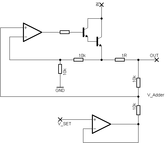
Rsense will cause Q2 to conduct when a threshold of approximately 0.65V is reached. Rbias will determine the extent of this limitation, although this aspect remains unclear. Particularly, if Rsense is positioned on the high side, simply activating Q2...
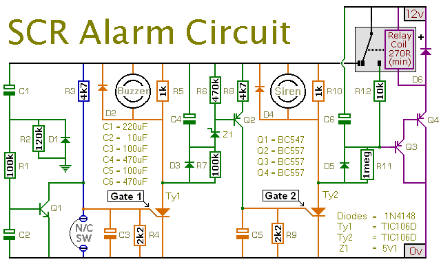
This is a simple SCR-based burglar alarm circuit. Its features include automatic exit and entry delays, along with a timed bell cut-off and reset. It is designed to be used with standard types of normally-closed input devices such as...

The FM497 is an integrated electronic ignition controller designed for breakerless ignition systems that utilize Hall effect sensors. This device operates an external NPN Darlington transistor to manage the coil current, thereby delivering the necessary stored energy while maintaining...
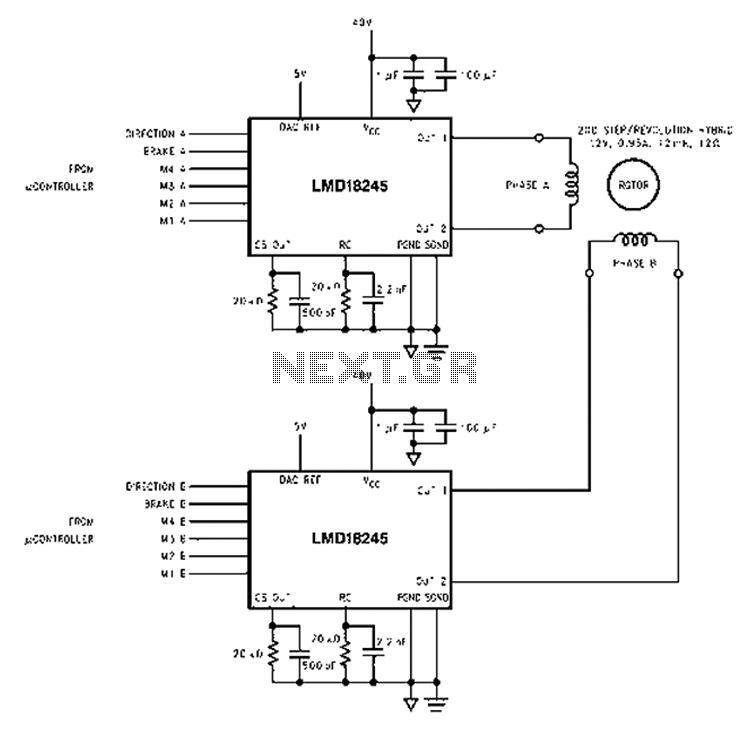
An innovative current detection method eliminates the power loss associated with the sense resistor in series with the motor. A 4-digit analog converter (DAC) facilitates digital control of the motor current path, simplifying the implementation of full, half, and...
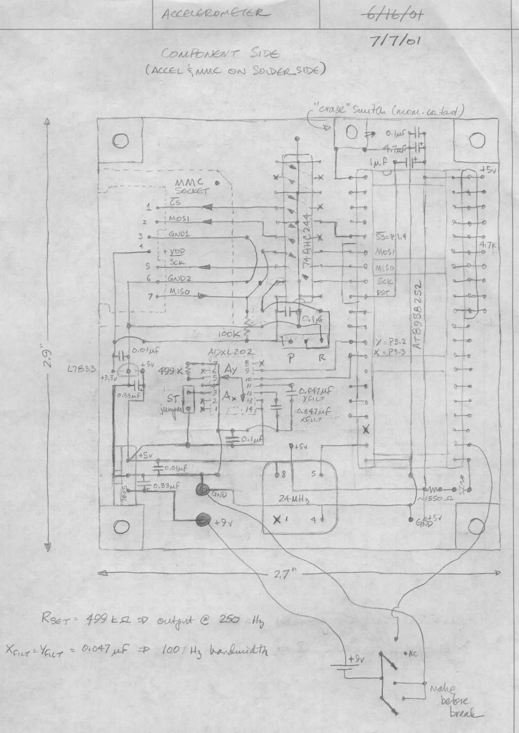
Below is a rough schematic of the layout of the accelerometer PC board looking from the component side. The microcontroller is an Atmel AT89S8252, an 8051 clone. This microcontroller is in-circuit programmable using an SPI interface. The SPI pins...
The circuit is conventionally designed with an eight LED audio level meter made from two low-power quad op-amps utilizing the LM324. Volume Unit. The eight LED audio level meter circuit serves as a visual representation of audio signal levels, providing...