
TDA1562Q 50W Car Audio Amplifier

The TDA1562Q is a high-performance integrated circuit designed for car audio applications, offering efficient amplification of audio signals. The amplifier operates in a bridge configuration, which allows it to deliver significant power output while maintaining sound quality. The circuit typically includes a power supply section, input stage, and output stage, along with necessary passive components such as resistors and capacitors to ensure stable operation and optimal performance.
In the described circuit, the two 1 kOhm resistors are likely used in the feedback loop to set the gain of the amplifier, while the two 4.7 kOhm resistors may be part of the input stage, providing impedance matching and ensuring that the input signal is appropriately conditioned for amplification. The amplifier's power supply should be capable of providing sufficient current to support the 50W output, typically requiring a voltage supply in the range of 12V to 14.4V, which is standard for automotive applications.
Additional components may include bypass capacitors to filter out noise from the power supply, as well as coupling capacitors to block DC offset from the input signal. The overall design must ensure thermal management, as the amplifier can generate heat during operation, necessitating proper heat sinking to maintain reliability and performance.
In summary, the TDA1562Q car audio amplifier circuit is a well-structured design that combines efficient power output with high fidelity audio reproduction, making it suitable for enhancing the audio experience in automotive environments. Proper implementation of the circuit components and adherence to design principles will ensure optimal performance and longevity of the amplifier.One car audio amplifier with TDA1562Q that can output 50W of audio power. TDA1562Q car amplifier circuit diagram 2 resistors 1 KOhms 2 resistors 4,7 KOhms.. 🔗 External reference
Related Circuits
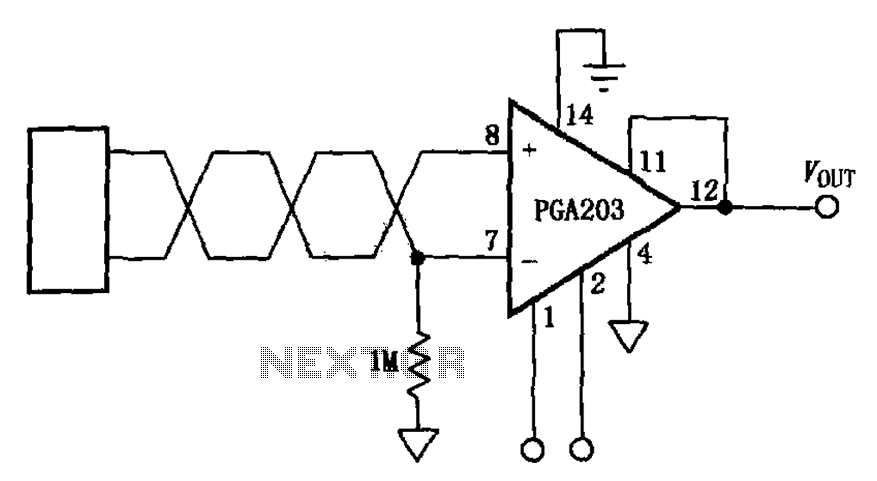
The circuit features a PGA203 programmable instrumentation amplifier. The input signal is applied to the twisted pair inputs of the PGA203, which subsequently amplifies the output signal. It is important to note that the input pins of the PGA203...
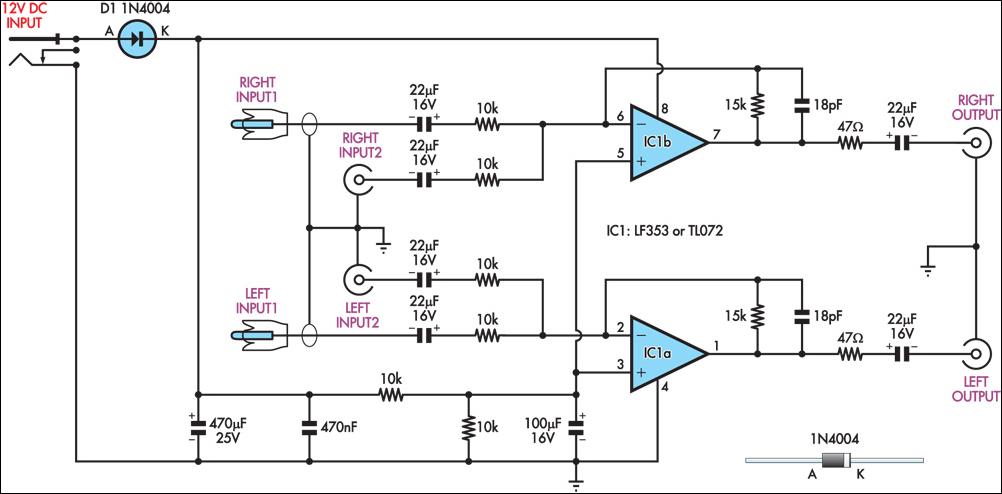
This circuit combines two separate line-level stereo (left and right) signals into a single stereo output, eliminating the need to switch between two sets of input signals. In this application, it is utilized to connect stereo audio from a...
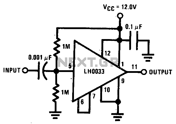
The input is DC biased to the mid-operating point and is AC coupled. Its input impedance is approximately 500K ohms at low frequencies. For DC loads referenced to ground, the quiescent current is increased by the load current set...
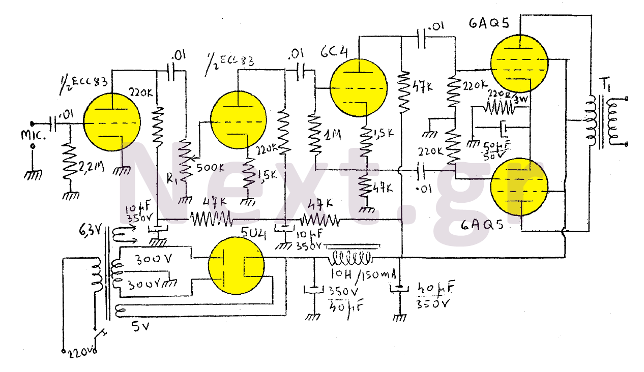
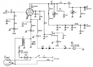
The output of this modulator consists of two 6AQ5 lamps arranged in a push-pull configuration with a maximum output of 15W. A 6C4 lamp is employed as a reversing lamp. The double-stage ESC83 serves as the pre-amplifier. The potentiometer...
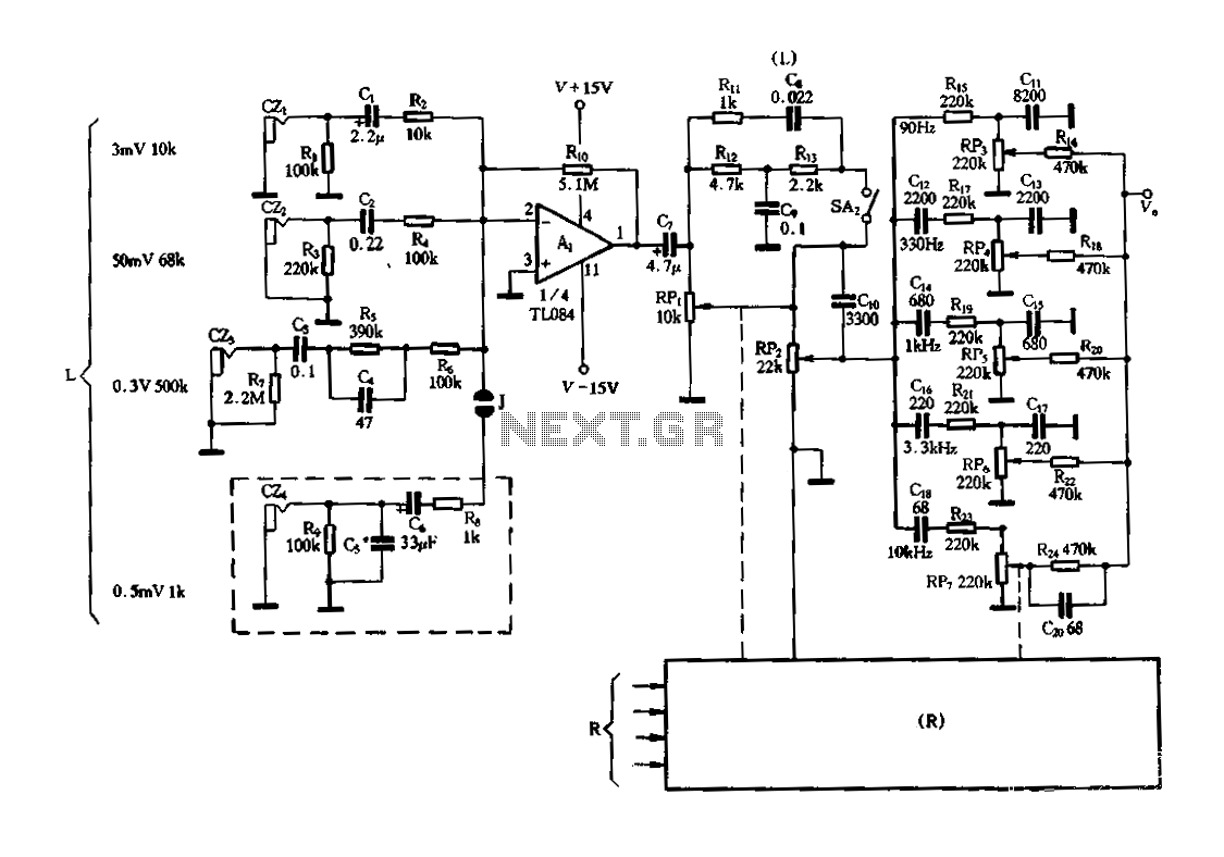
Figure 3-25 illustrates a hybrid circuit featuring four input preamplifiers. The components C1, C2, C3, and C4 can accept signals from a microphone, line, phono, and crystal head respectively. The configuration allows for the individual or simultaneous entry of...
1500 Watt RF Amplifier circuit can be utilized to drive a transmitter antenna. It is also applicable for powering RF high power sources, microwave heating, and other uses. The 1500 Watt RF Amplifier circuit is designed to amplify radio frequency signals,...