
TDA2005 car audio amplifier circuit diagram project

The TDA2005 is a robust integrated circuit designed for audio amplification in automotive applications. This circuit diagram outlines a project for a car audio amplifier that utilizes the TDA2005 chip, which is known for its ability to deliver high-quality sound output with minimal external components.
The circuit typically includes the TDA2005 IC, power supply connections, input and output terminals, and a few passive components such as resistors and capacitors. The power supply for the amplifier usually operates at 12V, which is standard for automotive systems. The input signal can be sourced from a car stereo or other audio devices.
The TDA2005 features built-in thermal overload protection, short-circuit protection, and a low noise output, making it an ideal choice for car audio applications. The output stage can deliver up to 10W of power into a 4-ohm load, which is sufficient for driving car speakers effectively.
Typical connections in the circuit include a bypass capacitor close to the power pins of the TDA2005 to filter out noise and stabilize the power supply. The input signal is often coupled through a capacitor to block any DC offset, ensuring that only the AC audio signal is amplified.
The output stage connects directly to the speakers, with additional filtering capacitors to minimize distortion and improve sound quality. The layout of the circuit should be designed to minimize interference and ensure that the amplifier operates efficiently. Proper grounding techniques should be employed to reduce noise and improve overall performance.
This project serves as an excellent introduction to audio amplification circuits, demonstrating the principles of operation for a car audio amplifier while utilizing the TDA2005 chip's capabilities.TDA2005 car audio amplifier circuit diagram electronic project using few external electronic parts 🔗 External reference
Related Circuits
The amplifier of circuit uses negative current feedback. The load current depends mainly on the input signal and not so much on the impedance of the loudspeaker. The inductor current of the loudspeaker develops a voltage across R7. This...
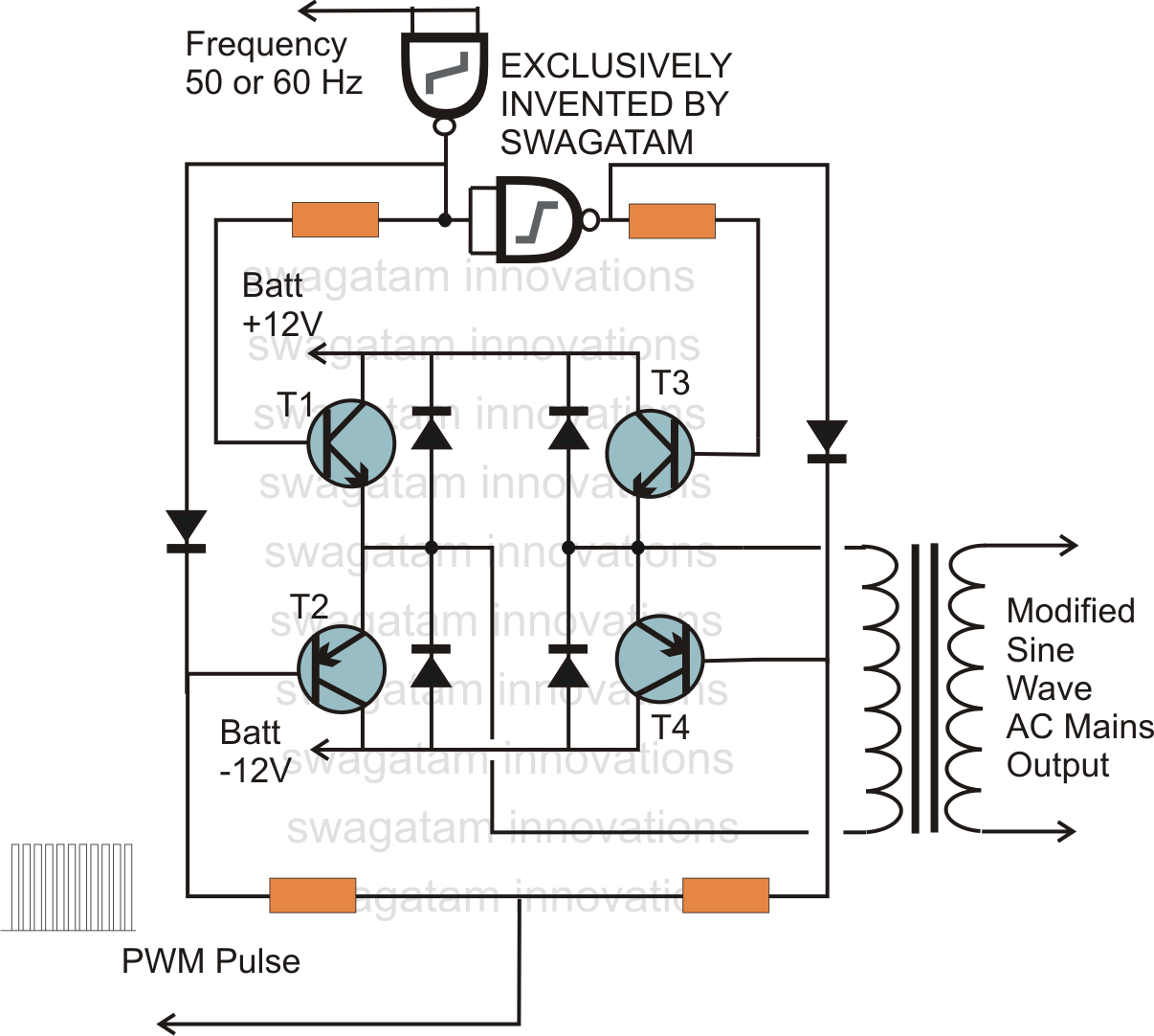
In electronics, an H-bridge circuit refers to a configuration consisting of four individual switching devices, such as transistors or MOSFETs, which can be controlled by external discrete signals from the respective stages of the control circuit. During operation, the...
This assembly is designed for amateurs who possess a collection of vinyl records and wish to convert them into a digital format on a personal computer. Alternatively, they may want to enjoy an old, cherished LP collection through their...
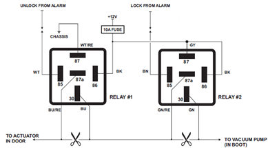
The circuit diagram displayed below illustrates a single-wire vacuum control system for pneumatic locking, commonly utilized in vehicles from Jaguar, Audi, and Mercedes. The circuit operates by managing the vacuum pressure required to engage or disengage the pneumatic locking mechanism....
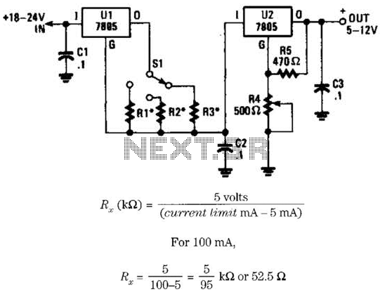
This voltage regulator and current limiter combination can be constructed using two 7805 regulators as illustrated. Resistors R1, R2, and R3 should be chosen to achieve a 5-V drop at the maximum allowable current limit. Switch S1 selects one...
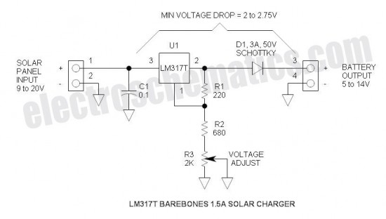
This is a simple and cost-effective solar battery charger that can be constructed by hobbyists. It has some limitations compared to other similar controllers, but it also provides several benefits. While primarily designed for charging lead-acid batteries, it can...