
Automotive Pneumatic Locking Circuit Configuration Diagram

The circuit operates by managing the vacuum pressure required to engage or disengage the pneumatic locking mechanism. It consists of a vacuum source, a control valve, and a locking actuator. The vacuum source is typically connected to the vehicle's engine or a dedicated vacuum pump, which generates the necessary vacuum pressure.
The control valve is an electromechanical component that regulates the flow of vacuum to the locking actuator. It is activated by a switch, which can be integrated into the vehicle's central locking system or operated manually. When the switch is engaged, the control valve opens, allowing vacuum pressure to flow towards the actuator, which then engages the locking mechanism.
The locking actuator is a diaphragm or piston-based device that responds to the applied vacuum. When vacuum pressure is present, the actuator moves, either locking or unlocking the door or trunk. The system is designed to ensure that the locking mechanism operates reliably and efficiently, providing enhanced security for the vehicle.
Additionally, safety features may be incorporated into the design to prevent accidental activation or failure of the locking system. These may include pressure sensors, fail-safe mechanisms, and feedback systems that confirm the locking status. Overall, the single-wire vacuum control circuit is an effective solution for pneumatic locking in high-end automotive applications.The circuit diagram shown below appears one wire vaccum control of pneumatic locking which is popular with Jaguar, Audi and Mercedes Pneumatic 🔗 External reference
Related Circuits
When this thermometer is utilized in a room environment, it operates intermittently, maintaining this operational state within the temperature measurement circuit due to the stable internal temperature. The astable multiresonance oscillator is composed of transistors VT1 and VT2, forming...
During rainy seasons, it can be quite bothersome when the car wipers operate continuously without pause. Have you ever considered implementing speed control for the wipers? While there are wiper control modules available commercially, many of them can be...
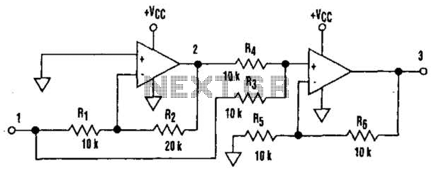
It is well understood that utilizing single-supply operational amplifiers (op amps) can present challenges when implementing simple functions in a bipolar signal environment. Often, this necessitates the use of additional op amps and other electronic components. Considering this, it...
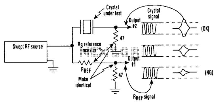
Occasionally, microprocessors and microcomputers may not be compatible with certain microprocessor crystals. Many data sheets for microprocessors specify maximum values for a crystal's equivalent series resistance (Rs), which may not be met by some crystals marketed for use with...
Gates U1-a and U1-b of the 4093 quad 2-input NAND Schmitt trigger are connected in variable, low-frequency square-wave oscillator circuits. The output of gate U1-a is connected to one of the inputs of gate U1-b. The square-wave output of...
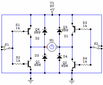
You have 4 transistors, wired as ON OFF switches. Two signal lines allow you to run the motor in one direction, when reversed, the motor runs in the other direction. It's very straightforward to use and build, but be...