
um3561 high temperature detector circuit diagram

The heat detector alarm circuit integrates several key components to ensure effective operation. The UM3561 sound generator IC is pivotal for generating alarm sounds, simulating a fire engine siren when triggered. The circuit architecture begins with the temperature sensing mechanism, where the T1 transistor acts as the primary heat sensor. This transistor is configured in a way that its conduction state is influenced by the ambient temperature. As the temperature rises, the T1 transistor's collector-emitter resistance drops, leading to increased current flow.
The T2 transistor serves as a secondary amplifier and relay driver. Its base is connected to the collector of the T1 transistor, creating a feedback loop that enhances the sensitivity of the heat detection process. When T1 conducts due to elevated temperatures, T2 also turns on, energizing the RL1 relay. The relay acts as a switch that controls the power to the siren, allowing it to produce an audible alarm.
Powering the circuit requires a stable 6 volts DC supply, which can be achieved using a standard battery or a regulated power adapter. The UM3561 IC, however, operates at a lower voltage, necessitating the inclusion of a 3-volt zener diode in the circuit. This zener diode regulates the voltage supplied to the UM3561, ensuring that it receives the correct amount of power to function effectively without risk of damage.
Overall, the design of this heat detector alarm circuit emphasizes simplicity and reliability, making it suitable for various applications in fire safety systems. The use of common electronic components facilitates easy assembly and troubleshooting, while the incorporation of transistors and a relay allows for efficient heat detection and alarm activation.This heat detector alarm electronic project is designed using the UM3561 sound generator circuit and some other common electronic parts. This heat detector circuit project uses a complementary pair comprising npn and pnp transistor to detect heat.
When the temperature close to the T1 transistor is hot, the resistance to the emitter collector goes low and it starts conducting. In same time T2 transistor conducts, because its base is connected to the collector of T1 transistor and the RL1 relay energized and switches on the siren which produce a fire engine alarm sound. This electronic project must be powered from a 6 volts DC, but the UM3561 IC is powered using a 3 volt zener diode, because the alarm sound require a 3 volts dc power supply.
🔗 External reference
Related Circuits

The battery-operated black light utilizes a U-shaped, unfiltered black-light tube, which requires approximately 250 Vac for operation. To generate the 250 Vac from a 6-V battery, the circuit employs a one-transistor blocking oscillator that drives a ferrite inverter transformer....
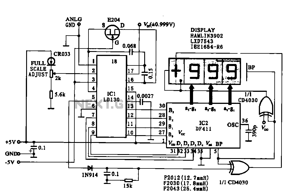
This circuit illustrates a display driving system for a digital voltmeter. The liquid crystal display (LCD) does not emit light by itself; it relies on external incident light for visibility. The integrated circuit (IC) LD130 serves as an input...
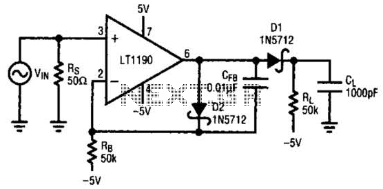
In this open-loop design, the detector diode is D1, and a level-shifting or compensating diode is D2. Load resistor RL is connected to -5 V, and an identical bias resistor RB is used to bias the compensating diode, also...

A UJT organ circuit with a circuit diagram is explained in detail. A 2N4891 UJT is used for the operation of the circuit. The UJT (Uni-Junction Transistor) organ circuit is designed to utilize the unique characteristics of the 2N4891 UJT...
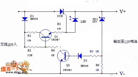
The circuit utilizes the positive half-cycle of an alternating current (AC) to charge a battery. It offers a rapid charging speed and has the potential to extend battery life. This charger is commonly used with standard motorcycles, demonstrating excellent...

Darlington phototransistor type light-sensitive switch control circuit application. The Darlington type phototransistor serves as a sensitive element, capable of detecting low light levels for the detection of reflected light signals. The Darlington phototransistor circuit utilizes a pair of transistors configured...