
Telemetering Beacon For VUSAT

The beacon controller circuit is structured to maximize efficiency and simplicity, ensuring reliable telemetering of data. The two CD4051 analog multiplexers are configured to handle the selection of 16 data channels, allowing for seamless transitions between different parameters. The 4-bit binary counter, typically implemented using a CD4017 or similar IC, ensures that each channel is selected in a systematic manner, driven by clock pulses that synchronize with the EOM signal.
The AD7574 ADC is a critical component, providing accurate conversion of analog signals to digital format. Its design allows for rapid conversion, which is essential for real-time data transmission. The RD! signal, which triggers the conversion process, is derived from the EOM signal, ensuring that data is only processed when a complete message has been transmitted.
The EPROM serves as a storage medium for Morse code data, structured into two distinct tables. The first table, with 256 entries, encodes various Morse messages, while the second table, with 16 entries, corresponds to channel identifiers. The encoding scheme uses binary representations for Morse code, where a dot and a dash are defined by specific bit patterns. For example, a dash is represented as 1110, while a dot is represented as 10. This encoding allows for efficient storage and retrieval of Morse code messages.
The CD4060 counter and oscillator work in tandem to generate the timing signals necessary for Morse code transmission. The oscillator's frequency is carefully chosen to ensure that the timing aligns with the standard Morse code timing conventions. The output from the counter provides the necessary address lines for the EPROM, facilitating the selection of the appropriate Morse code message or channel identifier based on the current operational state of the beacon controller.
In summary, the beacon controller is a well-structured system that effectively utilizes low-cost components to achieve its telemetering objectives. The careful design considerations ensure that ham radio operators can easily decode the transmitted Morse code without the need for complex equipment, adhering to the principles of simplicity and accessibility in electronic design.The beacon controller is intended to be operated for telemetering data available on board of the VUSAT in Morse code so that the ham radio operator can decode the info without any costly and complex equipment. The design strictly follows the KISS concept. It uses low cost, easily available components through out the design. A block diagram of the beacon controller is as shown: The controller can accept 16 single ended data channels of which the dc level represents the parameter to be telemetered. These channels are selected one by one (multiplexed) by using 2 number of CD 4051 (analog MUX). Voltage from selected channel is given to the ADC chip for converting this voltage to its digital equivalent.
A channel counter (4-bit binary counter) controls the channel selection. This counter counts every clock pulse given to it and thus gives a 4 bit binary output. This binary is given to the analog mux as address of the channel to be selected. For every clock pulse to the counter, successive channels are selected. The channel select clock is derived from the end of message signal (EOM), which will be explained later. ADC chip used is AD7574. This chip is an eight bit Successive Approximation type ADC made by `Analog Devices`. This ADC starts converting the analogue voltage input when the RD! signal goes low and the digital value is available at the output pins approximately 15 microseconds later.
RD! signal is derived from the "EOM" signal available from the EPROM. Eight-bit Binary output from ADC is given as the address of 8 most significant bits of the EPROM through two nos. of quad 2 input multiplexer chips. This two chips form an 8 bit 2 input multiplexer, one input is being the 8 bit binary from ADC and the other being the channel address (4 LSBs the upper nibble are made LOW).
This digital MUX selects either the value of the input channel (binary from ADC) or the channel number (4 bit address from channel counter). The selection is also controlled by the control logic that derives the control from the EOM signal from EPROM.
EPROM with 8-bit output stores the Morse code data in look up table form. Only one bit output is used to generate the Morse code and one more bit is used to generate EOM. The memory cell inside the EPROM is divided into two tables. The first table is the "Channel value " table that has 256 rows. Each row represents a message in Morse coded with binary bits. Each row is addressed by using 8 bit binary numbers. A key up condition is coded as `0` and key down as `1`. One can encode Morse code like this and a dash can now be represented as 1110 and a dot can represent as 10 where as a letter space as 000. For example the first entry in this table represents the number "zero zero zero" and to be coded as "111011101110111011100" Similarly table 2 contains a 16 rows, each row represents the channel number/ name encoded with bits as explained above.
If we want to transmit the Morse code for an input channel number/name, then table 2 is selected and the channel address from 7493 is given as the address for table 2 to select the wanted row of messages. Now the string of bits from this row is to be given out one by one sequentially. The counter IC CD4060 does this. This IC contains a multistage counter and an integrated oscillator. This counter is used as a 6 bit binary counter (counts from 0 to 63). The oscillator time period is selected is equal to the dot period (about 120 HZ). So when this counter is enabled, it starts from its reset state of 000000 and counts upwards until it is reset.
This Morse counter output form the least 6 bits of address to the EPROM. Seventh address bit of the EPROM is used to select the either the table 1 (when this bit is zero) or the table 2 (this bit is 1). The EPROM memory is thus segmented to form two tables with 256 entries in the first and 16 entries in the second as shown below: EOM: An end of message (EOM) is available
🔗 External reference
Related Circuits
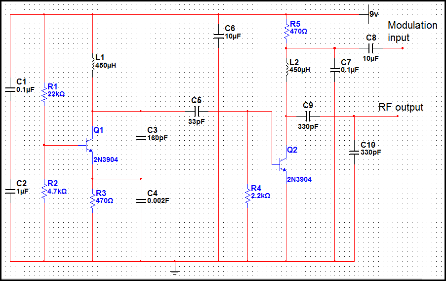
The transmitter operating at 2 meters (144 MHz) was primarily designed for use by radio amateurs as a radio beacon. It generates a high-quality signal suitable for this purpose. The 2-meter transmitter circuit typically includes several key components to ensure...
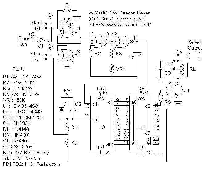
This circuit stores a single morse code message as bits in an EPROM chip, the message is sent to a relay which can key a CW transmitter. The keyer can output either a one-shot message such as "CQ DX...
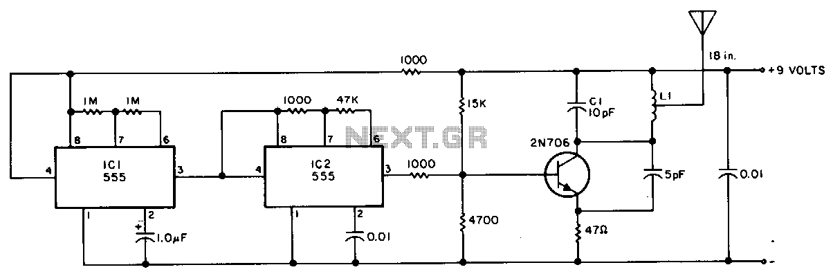
This transmitter is suitable for transmitter hunts, remote key finding, or radio telemetry in model rockets. It can be tuned to the two-meter band or other VHF bands by adjusting capacitor C1 and inductor L1. L1 consists of four...
The beacon is currently utilizing a simple Continuous Wave (CW) keying QRSS3 at a frequency of 10140.020 kHz, with a power output of 20 milliwatts. The PIC program used is PicBeacon developed by Ik2pcb. The concept for this beacon...
DDS VFOs are highly compatible with single conversion SSB radios, including models such as the Codan 6801, 6924, 7727, and 8121, as well as the AWA Teleradio 110H. Additional details regarding suitable Codan radios can be found on the...
The radio beacon band ranges from 280 to 516 kHz. Each beacon transmits a unique AM-modulated Morse-coded callsign on a designated frequency. To receive distant beacons, the aerial signal is processed through a band-pass filter that effectively attenuates longwave...