
Pulse DemodulatorCircuit

The Pulse Demodulator utilizing a CMOS Hex Inverter is designed to extract the envelope of amplitude-modulated signals. The hex inverter configuration allows for multiple signal processing paths within a single integrated circuit, enhancing the efficiency and compactness of the design.
In operation, the incoming amplitude-modulated signal is fed into one of the inverter inputs. The CMOS technology ensures low power consumption and high noise immunity, making it suitable for various applications where precision and reliability are critical. The inverter effectively inverts the input signal, producing a square wave that represents the envelope of the original amplitude-modulated signal.
The output from the inverter can be further processed by additional filtering stages to smooth the signal and retrieve the original modulation information. Capacitors and resistors may be employed in conjunction with the inverter to establish time constants that define the response time of the envelope detection.
This Pulse Demodulator circuit finds applications in communications systems, where it can be used for demodulating signals in radio frequency transmissions, as well as in various signal processing tasks requiring envelope detection. The versatility of the CMOS Hex Inverter makes it an essential component in modern electronic designs focused on signal integrity and efficiency.As is shown in the picture, the Pulse Demodulator is composed by CMOS Hex Inverter. This circuit can be used to process envelop detection on Amplitude Pulse.. 🔗 External reference
Related Circuits
This is a schematic diagram of a pulse width to analog demodulator circuit. This circuit is used to demodulate the pulse width to an analog voltage level. The pulse width to analog demodulator circuit is designed to convert pulse-width modulated...
This circuit is quite effective for testing or operating counters and stepping relays, as it eliminates the need for manually setting a switch for the desired number of pulses. By pressing the appropriate switches S1 to S9, one can...
The pulse width of the compact pulse cum frequency modulator can be adjusted by changing the switch-over point of comparator IC1 using a control voltage through resistor R1. The hysteresis of the IC is set by resistors R3 and...
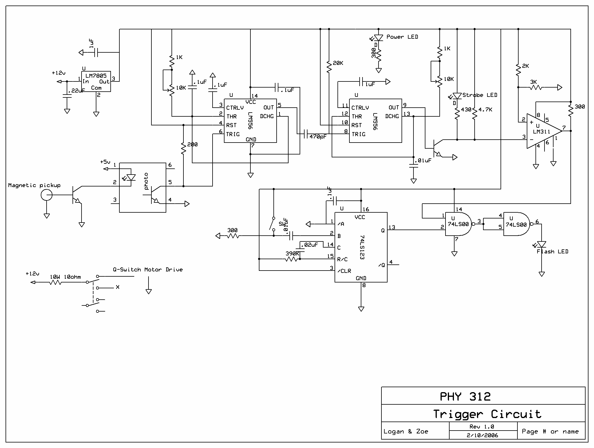
The ruby laser is a pulsed laser that produces very short pulses (a few nanoseconds), enabling the creation of holograms of various objects, including those that typically cannot be holographed. Conventional beam lasers require completely stationary objects; any slight...
This circuit operates as a 9V DC power source supplying a 555 timer to generate a square wave. The output is then processed through a Half-Wave Series Multiplier (Villard Cascade) to achieve a high voltage DC output. The goal...
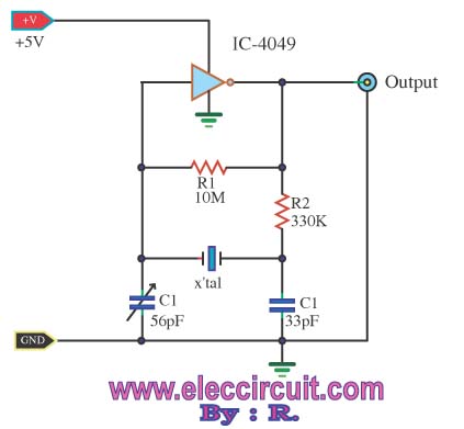
A friend requires a pulse generator oscillator circuit that maintains a stable frequency of 32.768 kHz for a digital CMOS binary counter. The pulse generator oscillator circuit designed to operate at a frequency of 32.768 kHz is commonly used in...