
Telephone Amplifier

The described amplifier circuit is designed to enhance audio signals, particularly in communication systems such as telephony. It typically employs a configuration that includes operational amplifiers or transistors to achieve the desired gain and frequency response characteristics.
The frequency response of the amplifier can be tailored by selecting appropriate values for capacitors C2 and C4. These capacitors are integral in shaping the amplifier's bandwidth and ensuring that it effectively amplifies the desired speech frequencies while attenuating unwanted high-frequency noise. For example, increasing the capacitance of C2 may lower the cutoff frequency, allowing more low-frequency signals to pass through, which is beneficial for capturing the nuances of human speech.
Moreover, the addition of a capacitor across resistor R4 serves to limit the high-frequency response of the amplifier. By specifying a capacitor value of approximately 33 pF, the circuit can effectively filter out frequencies that are beyond the voice band, which typically ranges from 300 Hz to 3 kHz. This filtering is crucial in maintaining clarity and intelligibility in speech signals, thereby enhancing the overall performance of the amplifier in telephone applications.
In summary, the amplifier's design allows for flexibility in frequency response adjustments through the careful selection of component values, ensuring optimal performance for speech amplification tasks. This amplifier can be used in telephone work or where a simple speech amplifier is required. The frequency response can be varied by the value of C2, C4, and addition of a capacitor across R4 (« 33 pF for voice band) to limit the HF response.
Related Circuits
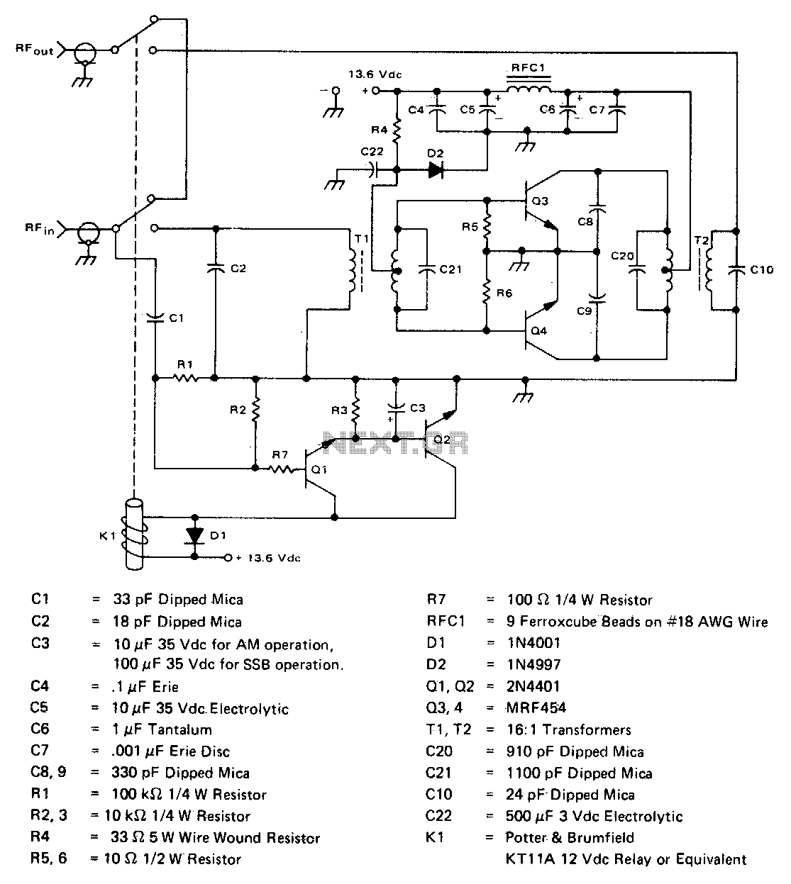
This inexpensive, easy-to-construct amplifier utilizes two MRF454 devices. It is specified for an 80 W power output with a 5 W input drive at a frequency of 30 MHz and operates on a 12 V DC supply. The amplifier circuit...
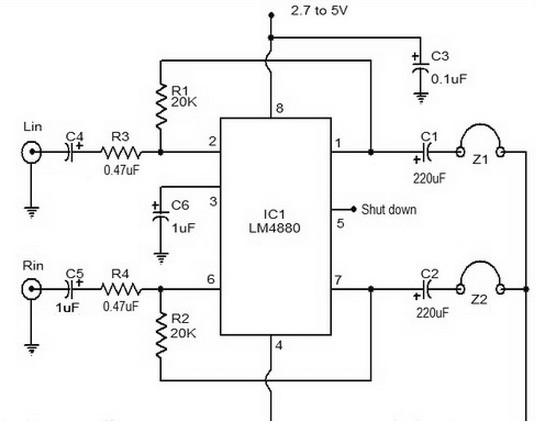
The LM4880 is a dual audio HiFi amplifier integrated circuit from National Semiconductor. This headphone amplifier circuit is specifically designed to produce high-quality audio output with a minimal number of components. The LM4880 integrated circuit is capable of delivering...
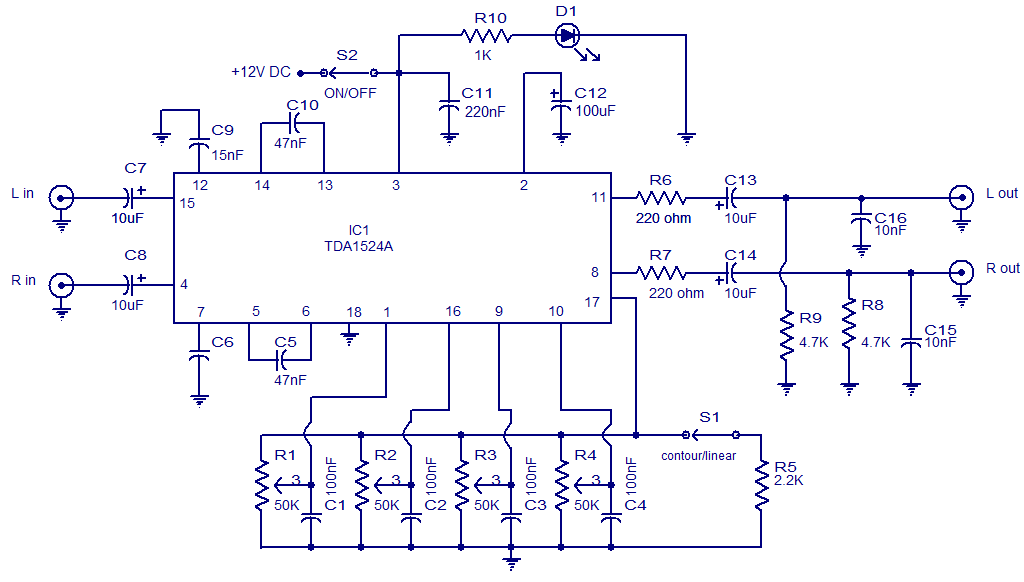
The following circuit illustrates the TDA1524 IC Stereo Preamplifier Circuit Diagram. Features include the ability to control volume, balance, and bass. The TDA1524 is a highly integrated stereo preamplifier IC designed for audio applications. This circuit configuration allows for the...
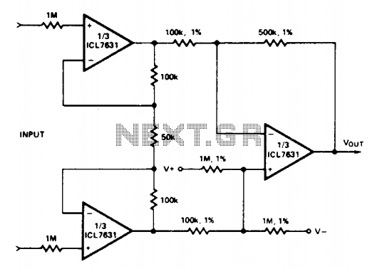
Input current (from sensors connected to the patient) is limited to less than 5 µA under fault conditions. Note that Avol = 25 single Ni-cad battery operation. The circuit is designed to ensure that the input current from patient-connected sensors...
Individuals seeking private listening to their music should incorporate this Headphone Amplifier into the Modular Preamplifier chain. The circuit design prioritizes simplicity while ensuring high-quality performance. This objective is achieved through the use of two NE5532 Op-Amps, where IC1B...
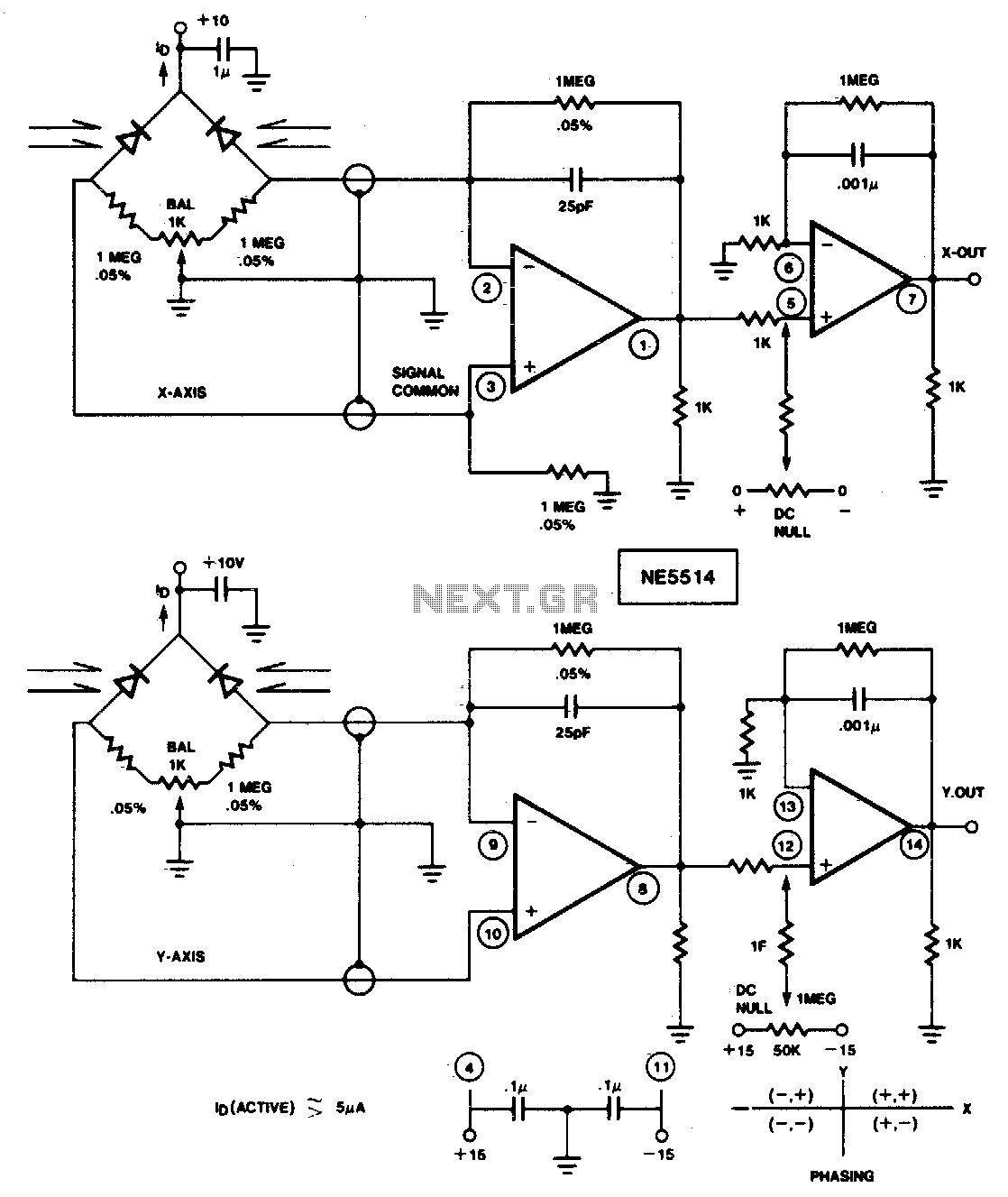
This circuit is designed to detect four-quadrant motion of a light source. By appropriately summing the signals from the X and Y axes, the resulting four-quadrant output can be utilized with an X-Y plotter, oscilloscope, or computer for simulation...