
Telephone electronic ringer circuit
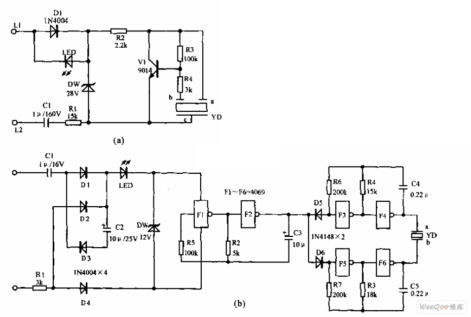
The telephone electronic ringer circuit operates by utilizing an NPN transistor as the switching element, which is pivotal for generating the ringing sound. The transistor is configured to amplify the signal received from the telephone line when an incoming call is detected. The choice between the 9014 and 3DG12 transistors depends on the desired specifications, such as current handling and switching speed.
The sound device YD is integral to the circuit, acting as the output transducer that converts the electrical signal into audible sound. The feedback mechanism, facilitated by the feedback pole, ensures that the circuit remains stable and produces a consistent ringing tone. The buzzer is specifically designed to resonate within the sound chamber, enhancing the overall sound quality and volume produced by the circuit.
Components L1 and L2 are typically inductors that help in filtering and stabilizing the current flowing through the circuit, ensuring that the ringing signal is clear and free from interference. Capacitor C1 and resistor R1 are crucial for controlling the voltage levels within the circuit, preventing any potential damage to sensitive components by limiting the maximum voltage and current.
Overall, this telephone electronic ringer circuit is a compact and efficient design that leverages the properties of transistors and passive components to deliver reliable performance in signaling an incoming call. Proper selection and configuration of the components are essential for achieving optimal functionality and sound output.Telephone electronic ringer circuit is shown as above,Figure (a) is the electronic ring circuit with an NPN transistor V1 (choose 9014 or 3DG12) as the core, sound devices YD is also feedback devices composed of the feedback pole and the buzzer equipped with the help of the sound chamber. L1, L2 connect to circuit line;C1 and R1 have limiting and reducting v.. 🔗 External reference
Related Circuits
The Link circuitry is simple and efficient, employing just two integrated circuits (ICs), a few transistors, and common components. It operates on 12 volts and is easy to assemble. This intercom system can connect various locations such as the...
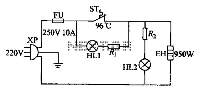
The 220V electric vibrator features a clip for insertion, with FU representing the fuse. ST indicates an inverter-like device, while HL1 and HL2 serve as indicators for insulation and heating. The EH component functions as the heater. When the...
This circuit employs a phototransistor along with four operational amplifiers to function as a total energy detector. It is designed to measure the total energy of optical pulses transmitted through an optical cable communication system. When the light intensity...
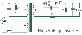
A 3V to 1000V inverter circuit has been constructed, but it is not functioning as intended. The creator seeks expert assistance to identify potential errors in the circuit design. Additionally, there is uncertainty regarding the transformer construction, as the...

The circuit illustrated here demonstrates that, despite advancements in components and technology, it remains possible to design effective and intriguing circuits. This design utilizes two well-known transistors, the BF256C and the BF494. Along with the necessary resistors and capacitors,...
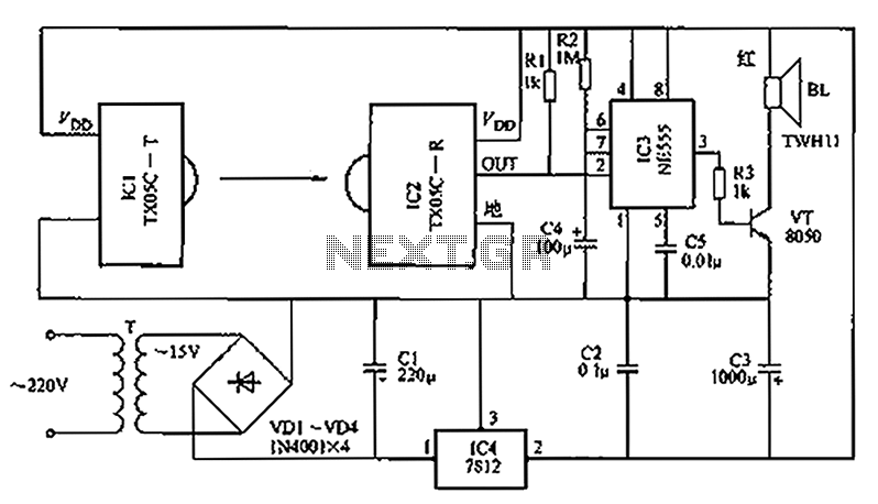
A new type of infrared system utilizes the TX05C radio sensor module for a burglar alarm designed for doors and windows. This system operates in the infrared spectrum, which is invisible to the human eye, making it suitable for...
Warning: include(partials/cookie-banner.php): Failed to open stream: Permission denied in /var/www/html/nextgr/view-circuit.php on line 713
Warning: include(): Failed opening 'partials/cookie-banner.php' for inclusion (include_path='.:/usr/share/php') in /var/www/html/nextgr/view-circuit.php on line 713