
Telephone in-use indicator

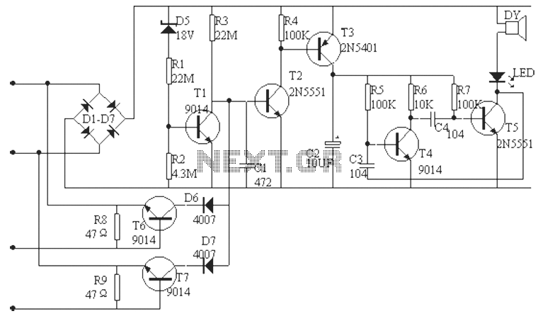
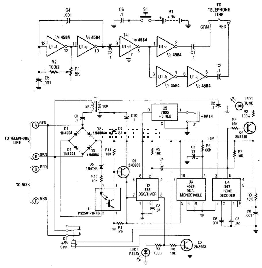
The line-current sensor circuit is designed to monitor the current flowing through a telephone line, allowing it to detect when the line is in use. The circuit typically includes a current sensing element, such as a shunt resistor or a Hall effect sensor, which generates a voltage proportional to the line current. This voltage is then processed by a comparator or microcontroller to determine the status of the line.
To ensure proper functionality, the circuit must be connected in series with the telephone line. This means that the circuit is placed before all phones on the line, allowing it to sense the current drawn when any phone goes off-hook. When the current exceeds a certain threshold, indicating that a phone is in use, the circuit can activate an indicator, such as an LED or a relay, to signal that the line is occupied.
The power supply for this circuit is derived from the telephone line itself, which typically provides a nominal voltage of around 48 volts DC when idle. This voltage is sufficient to power the circuit without requiring an external power source. The inclusion of an off-hook indicator at each phone can enhance the usability of the system, providing a local visual cue that the line is currently in use.
In summary, this line-current sensor circuit is a practical solution for monitoring telephone line usage and can be effectively implemented in both residential and commercial applications to improve communication management.This circuit functions as a line-current sensor and can be connected in series with either of the phone lines. For the circuit to indicate an "in use" status for all phones on a single line, it must be connected in series with the phone line before, or ahead of all phones on the line.
Since the power for the circuit is supplied by the phone company, a circuit could be added to each phone as an off-hook indicator.
Related Circuits
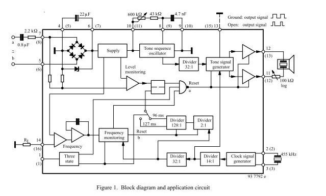
The three-tone ringing integrated circuit U4076B, in conjunction with a piezo transducer or loudspeaker, replaces the normal electromechanical telephone bell. It is operated with the ringing current frequency. The U4076B integrated circuit is designed to generate a three-tone ringing signal,...
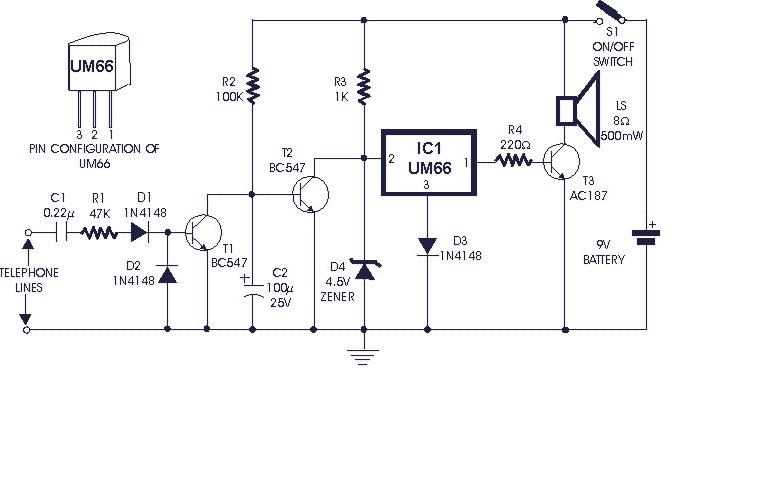
The standard telephone bell can be quite bothersome, especially at night when disturbance is undesirable. The circuit presented here transforms the loud ringing bell into a gentle and pleasant musical tone. This circuit utilizes a tone generator to replace the...
An audible field strength indicator (AFSI) allows users to listen to variations in radio signal strength, aiding in the detection of concealed antennas. This design utilizes inexpensive and readily available components, integrating a sensitive amplified field strength detection circuit...
The phone alarm device is designed to monitor and prevent unauthorized use of a telephone line. When interference signals are detected on the line due to theft attempts, the alarm activates, preventing the thief from making calls while alerting...
This system uses a transmitter operating at approximately 100 kHz to control a remote receiver. A line splitter can connect the transmitter to the active telephone line. The transmitter is a CMOS oscillator equipped with output buffer stages to...
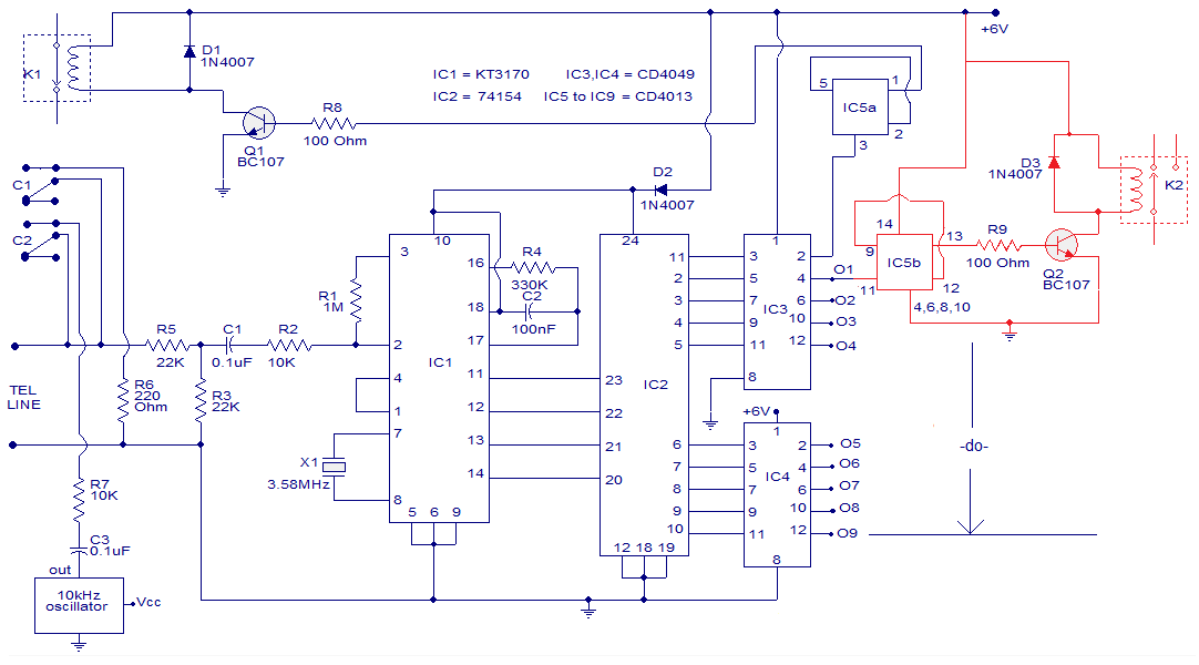
The circuit is a remotely operated DTMF telephone system capable of controlling up to nine devices using the keys 0 to 9 on a phone. The digit 0 is utilized to switch between the phone system remotely and alter...