
Telephone Intercom

The Link intercom system is a compact and versatile solution for communication across various settings, suitable for both casual and more structured environments. The use of a NE 556 dual timer IC allows for effective tone generation, ensuring that users experience a clear dial tone and ringing signal. The CD 4017B decade counter serves a critical role in interpreting the dial pulses generated by the handsets, effectively translating user inputs into actionable commands via the ringer circuits. The system's reliance on common components facilitates easy assembly and repair, making it an ideal project for hobbyists and professionals alike.
Powering the system with a 12-volt regulated supply ensures compatibility with standard electronic components while maintaining a low current draw, which is advantageous for battery-operated scenarios. The inclusion of opto-couplers enhances electrical isolation between the user interface and the control circuitry, improving safety and reliability. The four-wire configuration for the handsets allows for simultaneous speech and signaling, optimizing communication efficiency.
In summary, the Link intercom system exemplifies a practical and economical approach to local communication needs, combining simplicity in design with functionality, making it suitable for a wide range of applications from home use to institutional settings.The Link circuitry is simple and efficient, employing just two ICs, half a dozen transistors, and a handful of garden variety components. It all runs on 12 volts and is easily assembled. You can have your own home intercom between the kitchen, the garage, the rumpus room and at your poolside ?barby?
and all for less than $100! The ?Link? intercom has been designed in such a way that you can buy parts for it ?off the shelf? at just about any decent electronics retail chain. It uses old pulse dial handsets and replaces the AC bell set with a 9 volt DC buzzer. The whole circuit runs from a 12 volt regulated DC supply and is suitable for short term battery operation (eg: ?Gel Cell?). It is suitable for radio field days and sporting events (providing you can scrounge enough 4 wire cable) and may find a place in pre-schools, old folk?s homes, boy scout/girl guide halls, churches, kids? tree houses/fortresses, or maybe even more serious uses such as small offices, factories, workshops and many other applications.
The ?Link? is designed to enable one call at a time within a small area (about 100 meters from the ?black box? is about the max per handset) and is not suitable for connection to the PSTN (public network) as the voltages and currents used by the PSTN are higher, and will damage the simpler 12 volt circuitry, that employs CMOS ICs etc. The Link will run quite happily off a 12 volt regulated DC supply of only 200mA or so, and this can be a simple affair, such as a DC plug pack, wired to a 7812 regulator chip and appropriate filter caps on the output.
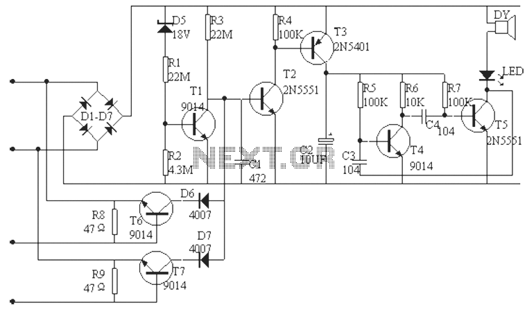
Add some leds if you want! The Link telephone intercom is designed around two ICs. The first, IC1, is an NE 556 dual timer chip, which is wired up to provide dial tone, ring tone (busy tone too, which will be explained along with a few add-ons to be mentioned later on) and ring pulses for the ringer circuit attached to each line circuit. The other chip, IC 2, is a CD 4017B decade counter, which is wired to count each train of dial pulses as they are received and buffered by the two opto-couplers, OC1 and OC 2 and their associated R/C networks.
Each phone handset is connected by a four wire circuit from the ?black box?. Two wires (normally tagged ?white? and ?blue? here in Oz) are for speech and dialing functions, whereas the other two (tagged locally as ?red? and ?black?) are for the ring pulses supplied by the ringer circuit to each DC buzzer inside the handsets. When a phone (eg: #1 for our discussion) is picked up in its ?off hook? condition, a DC loop is formed by the following components: DC circuitry inside the phone, the 1K winding of transformer TX, and back to 0V- earth.
Taken from the +12 volts terminal, through the Leds inside OC1 and OC2 and back to the phone handset. Dial tone is provided to the calling party?s phone when the Link is in its ?reset? condition (no calls in progress) via capacitor C3 and the 8 ohm winding (8R) of TX to 0v- earth. This and the other service tones are generated by IC1a, while ring pulses are generated by IC1b. When a calling party?s phone is ?off hook?, the leds force the photo transistors to switch on hard, pulling pins 13 and 14 of IC2 to 0 volts ground.
When the dial inside the phone handset is pulled back and released, the collector lead of OC2?s transistor is held low at 0 volts by the slow release charging of C5. Pin 13 of IC2 is a CE (chip enable) input, and needs to stay at a logic low (near 0 volts) to enable pin 14 to count the dial pulses.
So while ?impulsing? occurs, pin 13 stays low, and pin 14 alternates between logic high and low as the led emulates each dial pulse train, until the last pulse in the train is received. When caller number #1 dials phone number # 4, those four pulses appear across the leds inside OC1 and OC2.
The decade counter, acting as a Register (a storage device used in communications equipment for storing dialed digits) counts these pulses, turning its output pins on and off inn unison, with the last dial pulse causing the counter to rest on the last output pin that is turned on. The complete sequence for a maximum of ten pulses in the one pulse train, is (pin 3 is always at logic high at ?reset?) 2,4,7,10, and then 1,5,6,9,11 and then finally pin 3.
So when the number ?4? is dialed, the counter would step through pins 2,4,7, and then land on pin 10, which is connected to phone #4?s ringer circuit via Q4?s base lead. 🔗 External reference
Related Circuits
This compact circuit enables automatic recording of phone conversations. It connects to the phone line, the microphone input of a tape recorder, and the remote control jack of the recorder. The circuit detects the voltage on the phone line...
This LM386 circuit is modified into a simple Doophone intercom that can be built. In this doorphone circuit, an 8-ohm speaker is utilized. The LM386 is a low-voltage audio power amplifier, commonly used in various audio applications, including intercom systems....
The phone alarm device is designed to monitor and prevent unauthorized use of a telephone line. When interference signals are detected on the line due to theft attempts, the alarm activates, preventing the thief from making calls while alerting...

This simple circuit indicates the status of a phone, including Line OK, Dialing, and Call Attended. It also features a locking mechanism to block outgoing calls while allowing incoming calls, preventing misuse of the telephone. The circuit requires only...
Telephones are declining globally; however, India has over 350 million mobile phone users, alongside a significant number of traditional telephone users. This telephone timer is designed to save costs by controlling unnecessary time spent during phone calls. This simple...
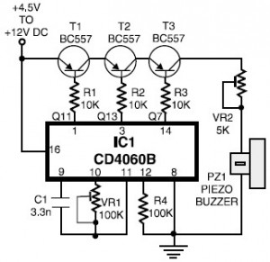
A telephone ring tone generator circuit is constructed using only a few components. This circuit simulates a telephone ring tone and operates with a voltage range of 4.5V DC to 12V DC. The telephone ring tone generator circuit typically includes...