
Relay type starting circuit diagram

The schematic involves a starting circuit that employs a relay to manage power supply activation. The circuit includes a power input connected to a resistor R, which plays a critical role in controlling the inrush current during startup. This inrush current is primarily influenced by the charging behavior of capacitor C1. The resistor R is strategically placed to mitigate the impact of high initial currents, thus protecting the power supply from potential damage.
In the initial phase of operation, when the circuit is powered, capacitor C1 begins to charge. The resistor R ensures that this charging process does not draw excessive current, which could lead to instability in the power supply. This is essential for maintaining the integrity of the power source during the brief startup period.
The relay J is designed to engage at a specific voltage threshold below 12V. When the circuit is powered, and the voltage is within this range, the relay activates, allowing the load to receive power temporarily. The operation of the relay is crucial, as it creates a path that bypasses resistor R once the capacitors C1 and C3 are sufficiently charged. This transition allows the circuit to enter a stable operating state, where the power supply can function without the constraints imposed by resistor R.
As capacitors C1 and C3 charge, the voltage across them increases, eventually reaching a level that allows the relay contacts to close, effectively short-circuiting the resistor R. This action not only stabilizes the circuit but also enhances the efficiency of the power delivery to the load. The design ensures that the system can handle the initial surge of current while transitioning smoothly to normal operation, thereby optimizing performance and reliability in the overall circuit function. As shown below, the following figure is the use of a relay or the like of the starting circuit. Power input access resistance R, R role there are two, one: to prevent boot when the impact of current large capacitor C1 affect the power supply itself; Second: Power-up the load eligible for a few seconds. In this process, due to the output of the relay J pull-in voltage of less than 12, from limiting the role of blood pressure combined R access to the circuit, with the power to C1, C3 is fully charged, the relay J pull short-circuit the contacts R, then, before the power supply into the normal working condition.
Related Circuits
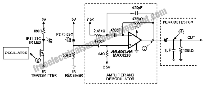
The following circuit illustrates an Infrared Proximity Sensor Circuit Diagram. This circuit is based on the MAX4230 integrated circuit. Features include a 10 kHz oscillator. The Infrared Proximity Sensor Circuit utilizing the MAX4230 integrated circuit is designed to detect the...
In the event of a sudden power failure in an elevator, it is crucial for the duty officer in the distribution room to be alerted promptly to prevent panic among passengers trapped inside. The following describes a sound alarm...
Figures (a) and (b) illustrate two basic oscillator circuits operating at 2 MHz. The circuit design allows for adjustment of the optimal operating point through testing. The two oscillator circuits depicted in the figures utilize different configurations to achieve stable...

This is a design for a scoring game circuit suitable for any occasion where dice are used. The circuit utilizes a NE555 timer, a 74LS192 counter, a 74LS247 decoder, and a seven-segment LED display. The timer IC1 generates a...
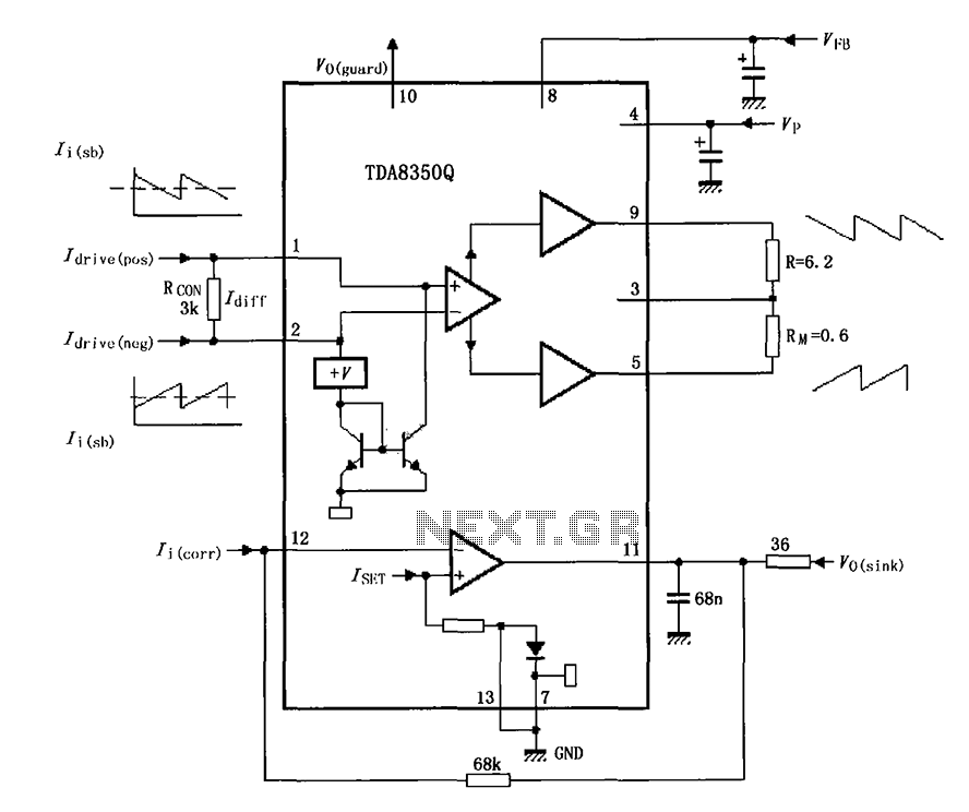
The TDA8350Q test circuit includes a push-pull amplifier configuration where the output terminal resistor serves as a dummy load for testing an alternative deflection coil. The TDA8350Q is a high-performance integrated circuit designed for use in television and display systems....
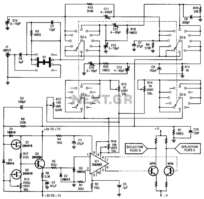
An oscilloscope front-end amplifier can be constructed using low-cost transistors and video amplifier integrated circuits (ICs). This preamplifier utilizes a FET input along with compensated attenuators, achieving an approximate bandwidth of 100 MHz, which is sufficient for most general-purpose...