
Telephone Ringer using 556

The described circuit utilizes two 556 timer ICs, which are dual versions of the popular 555 timer, to generate a series of modulated rectangular waveforms that mimic the ringing tones of a telephone. The astable multivibrator configuration is used to create the necessary waveforms, with the first multivibrator generating a pulse train characterized by a 1-second low state followed by a 2-second high state. This output governs the operation of the subsequent multivibrator, which further modulates the waveform to produce distinct ringing tones.
The circuit's design incorporates a resistor (R7) connected to the collector of transistor T2. This resistor plays a crucial role in maintaining a charge on capacitor C3, ensuring that it does not fully discharge when T2 is in a conducting state. This design consideration is essential for maintaining the integrity of the waveform generation.
The preset resistor (VR1) is adjustable and must be configured to yield two distinct ringing tones within a one-second interval, allowing for a customizable ringing pattern. The other two multivibrators are tasked with generating additional tones that correspond to the initial output pulses, creating a layered ringing effect.
Activation of the circuit is achieved by closing switch S1, which results in the cutoff of transistor T1, thereby initiating the pulse generation from the first multivibrator. It is important to note that if switch S1 is integrated into the power supply line, there may be a delay before the ringing tones commence, as the circuit requires time to stabilize.
While the circuit is designed to generate ringing tones, it is not intended for direct connection to telephone lines. Instead, it can be adapted for use with intercom systems or similar applications by implementing appropriate drive circuitry across switch S1. This ensures that the generated ringing pulses can effectively signal the intended recipient while maintaining a constant voltage level necessary for operation.Using modulated rectangular waves of different time periods, The circuit presented here produces ringing tones similar to those produced by a telephone. The circuit requires four astable multivibrators for its working. Therefore two 556 ICs are used here. The IC 556 contains two timers (similar to 555 ICs) in a single package. One can also assemble this circuit using four separate 555 ICs. The first multivibrator produces a rectangular waveform with 1-second low duration and 2-second high duration.
This waveform is used to control the next multivibrator that produces another rectangular waveform. A resistor R7 is used at the collector of transistor T2 to prevent capacitor C3 from fully discharging when transistor T2 is conducting. Preset VR1 must be set at such a value that the two ringing tones are heard in one second. The remaining two multivibrators are used to produce ringing tones corresponding to the ringing pulses produced by the preceding multivibrator stages. When switch S1 is closed, transistor T1 cuts off and thus the first multivibrator starts generating pulses.
If this switch is placed in the power supply path, one has to wait for a longer time for the ringing to start after the switch is closed. The circuit used also has a provision for applying a drive voltage to the circuit to start the ringing.
Note that the circuit is not meant for connecting to the telephone lines. Using appropriate drive circuitry at the input (across switch S1) one can use this circuit with intercoms, etc. Since ringing pulses are generated within the circuit, only a constant voltage is to be sent to the called party for ringing.
🔗 External reference
Related Circuits

The multifunction frequency meter is an instrument that can measure various parameters on a single display using an 8-digit 7-segment LED. The controls measure... The multifunction frequency meter is designed to provide accurate measurements of frequency, voltage, current, and other...

The circuit described uses a single chip, IC BA3812L, to realize a 5 band graphic equalizer intended for use in hi-fi audio systems. The BA3812L is a five-point graphic equalizer that integrates all the necessary functions onto one IC. The...
This circuit detects the dial tone from a telephone line and decodes the keypad pressed on the remote telephone. The dial tone heard when picking up the phone is referred to as Dual Tone Multi-Frequency (DTMF). This name originates...

This circuit for an intercom is a stand-alone electronic communications system designed for limited or private dialogue. The schematic illustrates the application circuit of the LM390 in the intercom configuration. Gain control can be achieved by capacitively coupling a...
The telephone repeater is a circuit designed to amplify the call signal, making it louder than the original. This circuit has been developed in response to specific requests. The telephone repeater circuit functions by receiving the incoming audio signal from...
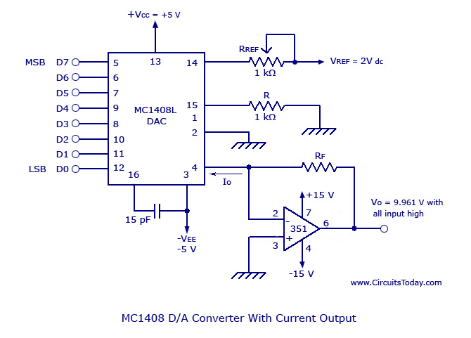
Monolithic/Hybrid Digital to Analog Converters using MC 1408 IC, SE/NE 5018, Specifications and Applications. Monolithic and hybrid digital-to-analog converters (DACs) are integral components in various electronic systems, facilitating the conversion of digital signals into corresponding analog voltages or currents. The...