
Telephone repeater circuits

The telephone repeater circuit functions by receiving the incoming audio signal from a telephone line and amplifying it to enhance the clarity and volume of the sound. The primary components of this circuit typically include a microphone for capturing the audio signal, an operational amplifier (op-amp) for amplification, and a speaker for outputting the enhanced sound.
In practical implementations, the circuit may utilize a power supply to ensure sufficient voltage levels for the op-amp, which can be configured to provide a desired gain. The circuit design may also include filters to eliminate unwanted noise and ensure that only the relevant frequency range of the audio signal is amplified.
To improve the performance of the repeater, feedback mechanisms can be incorporated to stabilize the amplification process and prevent distortion. Additionally, the circuit can be designed with user controls, such as volume knobs, to allow for adjustments based on individual preferences.
The telephone repeater is particularly useful in environments where the original sound is too faint, ensuring that the communication remains clear and effective. This circuit can be applied in various settings, including home telephony systems, public announcement systems, and any scenario where audio signals require amplification for better audibility.The telephone repeater or The call signal peripheral circuit to the loud than the original. It`s a circuit that we design follow the request. One of my friends 🔗 External reference
Related Circuits
The main objective of this system is to transmit message or text through ordinary Land Line Telephone from one end (source) to another end (designation). This is achieved by the DTMF technology. It has two sections: one for editing...
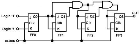
The circuit in Figure 1 is a 4-bit asynchronous counter, also known as a ripple counter. It consists of four J-K flip-flops with their J and K inputs connected to logic 1. This configuration causes the output of each...
Often a need arises for connection of two telephone instruments in parallel to one line. But it creates quite a few problems in their proper performance, such as overloading and overhearing of the conversation by an undesired person. In...
The resistors were not measured precisely, and given their ±5% tolerance, along with a Vref range of 1.2 to 1.3 volts, it is possible to exceed 6 volts in certain scenarios. A discussion arose regarding the effectiveness of these...
The given circuit, when connected in parallel to a telephone, displays the number dialled from the telephone set using the DTMF mode. This circuit can also show the number dialled from the phone of the called party. This is...
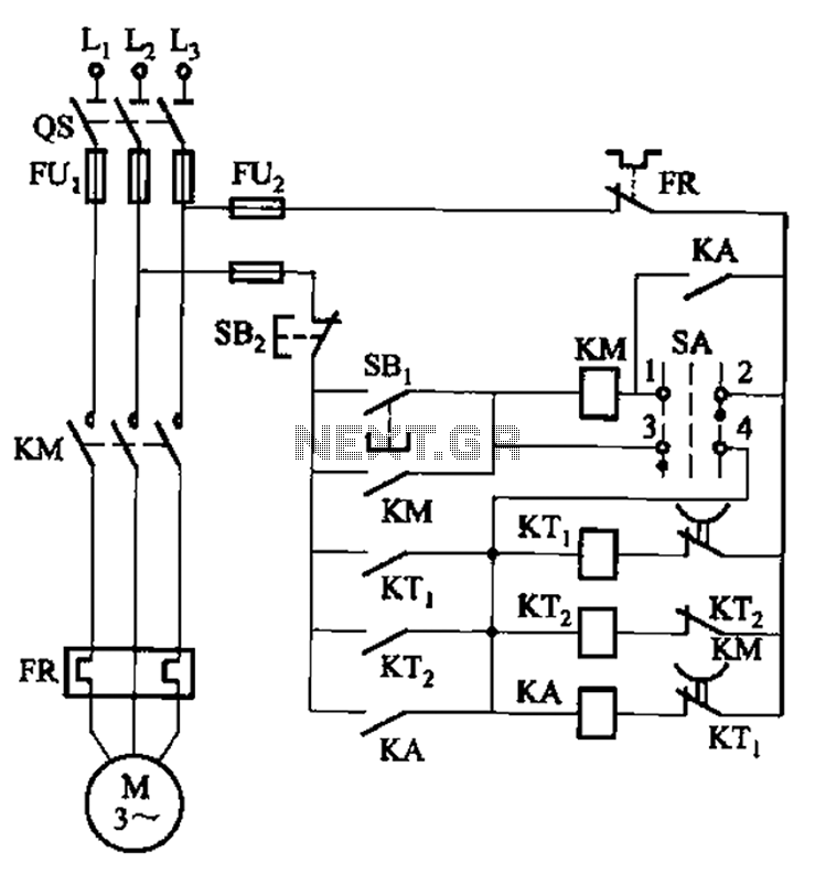
The circuit illustrated in Figure 3-78 utilizes two relays for automatic control, featuring a more complex line structure. This configuration allows for intermittent motor operation. Additionally, it can operate continuously when switch SA is positioned to the right. The circuit...