
XTR112 114 isolated transmit receive circuit diagram of the ring

The circuit design begins with the RTD (Resistance Temperature Detector), which is a temperature sensor that provides a resistance change proportional to temperature. The XTR112/114 is an integrated circuit specifically designed for converting the resistance change from the RTD into a corresponding voltage signal. This voltage is then converted into a standard 4 to 20 mA current loop output, which is a common industrial standard for signal transmission, allowing for long-distance signal integrity.
The twisted pair wiring used for transmission minimizes electromagnetic interference, which is crucial in industrial environments. Upon reaching the receiving end, the RCV420 module is employed to capture the 4 to 20 mA signal, ensuring that the signal is accurately interpreted. The ISO124 isolation amplifier serves to electrically isolate the output from the input, providing protection against surges and noise, and converting the current signal into a 0 to 5V voltage output suitable for further processing or display.
The circuit's design incorporates robust anti-jamming features, making it ideal for use in environments with substantial electrical noise, such as factories or near heavy machinery. The inclusion of a three-wire RTD configuration in the schematic allows for improved accuracy by compensating for lead resistance. In cases where a two-wire RTD is implemented, the design stipulates the removal of the RLIN2 resistor to maintain proper functionality and accuracy. This adaptability enhances the circuit's versatility in various applications, ensuring reliable temperature measurement and monitoring. As shown, collected at the scene RTD temperature, it is converted into a voltage by the XTR112/114 voltage is converted into 4 ~ 20mA current output, and then the twisted pair transmission, RCV420 reception, isolation amplifier ISO124 isolation amplifier, the output 0 ~ 5V voltage. Excellent anti-jamming performance of the circuit can be applied to long-distance transmission interference or big occasions.
The figure for the three-wire RTD connection, if the connection with the two-wire RTD, then remove RLIN2.
Related Circuits
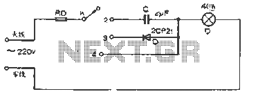
The figure illustrates a basic dimming lights circuit. The light intensity is controlled by a multi-speed control switch, designated as K. When switch K is set to position "1," the lights are turned off. In position "2," the light...
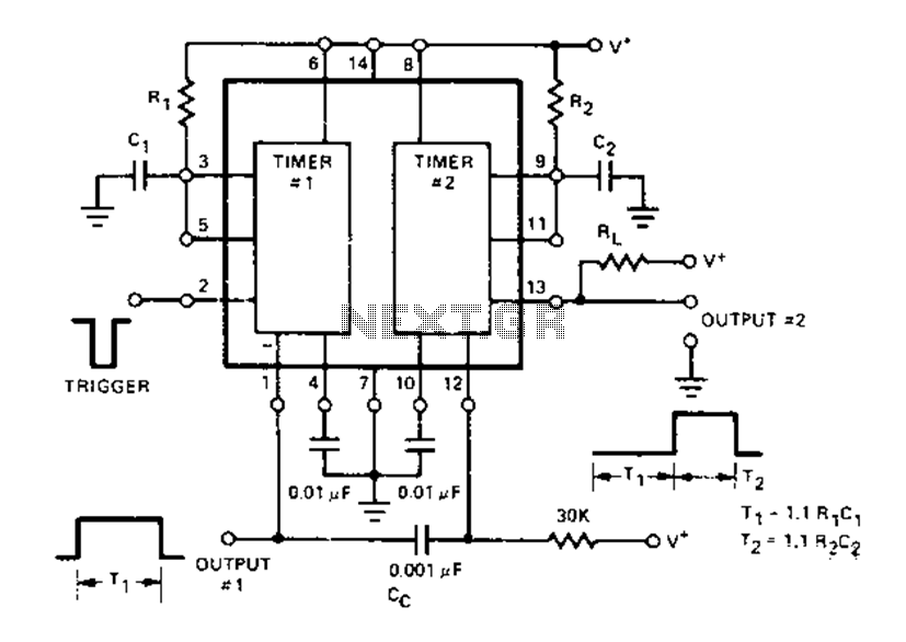
The Dual Timer Exar XR-2556 features a timing mechanism that can be triggered through capacitive coupling on a secondary timing pin. When a trigger input is engaged, the duration T1 can be set to 1.1R1C1, resulting in an increased...
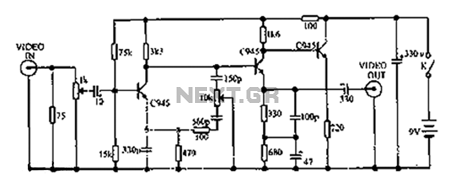
This circuit compensates for additional defects in image quality associated with LP (long play) recorders. The frequency components of the television signal reflect the details displayed on the screen. Enhancing the high-frequency components increases the edge sharpness of the...
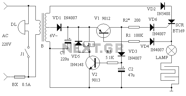
It is said that mice are more sensitive to electromagnetic fields, which is why high-voltage grids generally yield poor results in rodent control. The electronic rodent control system described here does not use high-voltage power lines, thus it does...
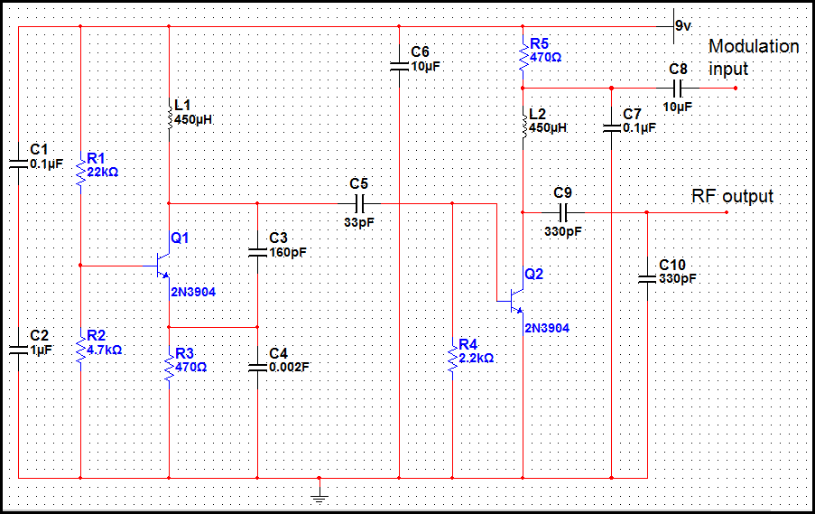
The transmitter operating at 2 meters (144 MHz) was primarily designed for use by radio amateurs as a radio beacon. It generates a high-quality signal suitable for this purpose. The 2-meter transmitter circuit typically includes several key components to ensure...
The circuit designed for distortion measurements eliminates the fundamental frequency of 1 kHz, enabling the assessment of the residual harmonic levels. Initially, a true RMS meter is employed to measure the 1-kHz input level (E^) by positioning the switch...