
Temperature-compensated crystal oscillator

The circuit utilizes a combination of two negative-coefficient capacitors to achieve a specific capacitance adjustment. Negative-coefficient capacitors exhibit a decrease in capacitance with an increase in voltage or frequency, which can be beneficial in certain applications where frequency compensation is necessary.
In this configuration, the two capacitors are strategically selected and connected in such a manner that their individual characteristics complement each other. By blending these capacitors, the circuit can effectively counterbalance the natural decrease in frequency associated with standard AT-cut crystal oscillators. The AT-cut crystal is commonly used in oscillators due to its favorable temperature stability and frequency characteristics. However, as the frequency of operation shifts, the need for capacitance adjustment becomes critical to maintain performance.
The design may include a variable resistor or a potentiometer to fine-tune the capacitance further, allowing for precise adjustments based on the specific requirements of the application. This flexibility ensures that the oscillator remains stable across varying conditions, thereby enhancing the overall reliability and performance of the circuit.
Proper attention must be given to the selection of the capacitors, ensuring that their temperature coefficients and voltage ratings are suitable for the intended operating environment. Additionally, the layout of the circuit should minimize parasitic inductances and capacitances to maintain signal integrity. This approach not only optimizes the frequency response but also contributes to the longevity and efficiency of the electronic system.Two different negative-coefficient capacitors are blended to produce the desired change in capacitance to counteract or compensate for the decrease in frequency of the "normal" AT-cut characteristics.
Related Circuits
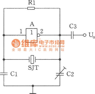
The image depicts a sine wave oscillator that consists of a quartz crystal (SJT) and gate A of the hex inverter IC CD4069. Compared to a standard RC phase-shift oscillator, the frequency stability of a crystal oscillator can achieve...
This simple, one-transistor amplifier provides a voltage gain of over 1000 (60 dB) for an active aerial impedance crystal earphone. The gain is achieved by replacing the standard load resistor with a constant-current diode that supplies 1/2 mA while...

The intent is to utilize the inductance of a standard telephone earpiece as the inductor (L) in a Colpitts oscillator, thereby removing the necessity for a separate amplifier or buffer. The Colpitts oscillator is a type of electronic oscillator that...
A crystal oscillator operates at a frequency of 51 MHz, which corresponds to the third harmonic of a 17 MHz fundamental frequency. Depending on the specific structure used, the drain-gate capacitance can be selected within a range of 0.5...
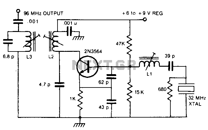
By utilizing a crystal oscillator operating between 27 and 33 MHz, the third harmonic frequency will produce an output ranging from 82 to 99 MHz. The implementation of a crystal oscillator within the specified frequency range of 27 to 33...
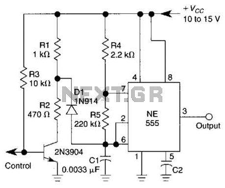
A 1-kHz gated oscillator with no long turn-on cycle is shown. R2, R3, and D1 preset the voltage on tuning capacitor C1 to a percentage of the supply voltage. The circuit described functions as a gated oscillator operating at a...