
Temperature compensation of the symmetrical power supply 7812 F007C

The described circuit operates as a precision voltage regulator, utilizing a combination of bipolar junction transistors (BJTs) for temperature compensation. The two transistors are configured in a way that their temperature coefficients offset each other, minimizing drift in the output voltage due to temperature variations. This configuration is critical in applications where voltage stability is paramount, such as in analog signal processing and precision measurement systems.
The operational amplifier in this circuit serves as a feedback controller, ensuring that the output voltage remains stable and responds accurately to changes in load conditions. By employing the F007C regulator, which is known for its low dropout voltage and high output current capability, the circuit can maintain regulation even under varying input conditions. The symmetrical output makes this design particularly advantageous for differential signaling applications, where both positive and negative voltages are required to maintain signal integrity.
In summary, this temperature-compensated power supply circuit is a robust solution for providing stable and symmetrical voltage outputs, making it ideal for high-precision electronic applications. Its design ensures that both the positive and negative outputs are tightly regulated and maintain high accuracy across a range of operating temperatures. As shown in Figure it is a temperature compensated with a negative voltage to follow the positive changes in the symmetrical voltage integrated power supply. This circuit is ch aracterized by: three-terminal regulator regulator circuit is connected with two of the same type transistors, using the temperature characteristics of the transistor PN junction temperature compensation with each other, so that a positive voltage output of the power supply has a high temperature stability and accuracy. Utilize the op amp and F007C regulator BG4 (3AD30B), the negative voltage accurately tracks the positive voltage changes, so that the positive and negative output voltage strictly symmetrical, and has a high accuracy.
The power supply is suitable for the symmetry of the positive and negative voltage requirements for higher electronic circuits.
Related Circuits
Another adjustment of application operational amplifiers to adapt a power supply is apparent below. The power supply requires an additional adjustment to supply the op-amps with a bipolar voltage (+/- 8 volts), and the negative voltage is also used...
This circuit indicates the power level delivered to a loudspeaker. A dual-color LED displays green at approximately 1 watt, orange at 1.5 watts, and bright red at levels exceeding 3 watts. The circuit is connected in parallel with the...
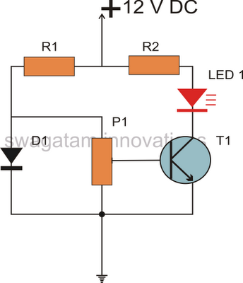
All semiconductors exhibit the tendency to alter their fundamental characteristics in response to changes in ambient temperature. Basic electronic components such as transistors and diodes are particularly susceptible to variations in case temperature. The alteration in their characteristics is...
The two circuits demonstrate the operation of opening a relay contact shortly after the ignition or light switch is turned off. The capacitor becomes charged, and the relay remains closed until the voltage at the diode anode reaches 12...
This circuit was designed and manufactured in the 1980s. Since then, it has operated without issues. There are no specific construction challenges, aside from the usual considerations: attention to the power supply requirements, selection of an appropriate heatsink, and...
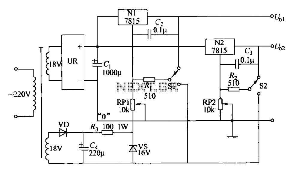
An adjustable dual voltage power supply circuit is presented, suitable for frequent experimental use. The current output does not exceed 1A, and both voltage outputs are adjustable. The circuit utilizes N1, N2, and 78 series three-terminal voltage regulator integrated...