
Temperature Control Circuit by Fan

The temperature control circuit utilizes a fan to maintain a desired ambient temperature within a specified range. The core components of the circuit typically include a temperature sensor, a microcontroller or comparator, a fan, and a display unit for temperature indication.
The temperature sensor, often a thermistor or a digital temperature sensor like the LM35, detects the current temperature of the environment. The sensor outputs a voltage or digital signal proportional to the temperature, which is then fed into the microcontroller or comparator. The microcontroller processes this input and compares it against a pre-set temperature threshold.
When the sensed temperature exceeds the threshold, the microcontroller activates the fan through a relay or a transistor switch, providing cooling to reduce the temperature. Conversely, if the temperature falls below the threshold, the microcontroller deactivates the fan to conserve energy and prevent overcooling.
The temperature indication is usually achieved through an LCD or LED display connected to the microcontroller. This display provides real-time temperature readings and may also include status indicators for the fan operation, such as an LED that lights up when the fan is active.
In addition, the circuit may incorporate features such as hysteresis to prevent rapid on-off cycling of the fan and a user interface for setting the desired temperature threshold. Power supply considerations, such as voltage regulators or power adapters, are also essential to ensure stable operation of the circuit components.
Overall, this temperature control circuit is an effective solution for maintaining optimal temperature conditions in various applications, from home automation systems to industrial processes.The circuit is temperature control by fan, this circuit can control temperature and it also indicates the temperature. All the above functions are monitored and. 🔗 External reference
Related Circuits
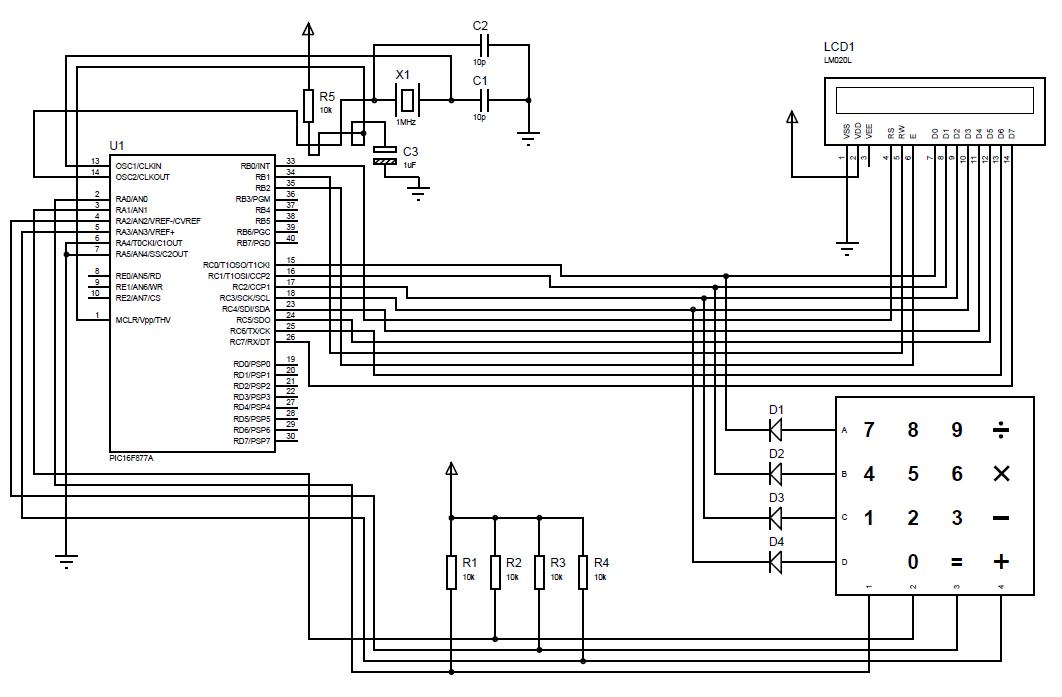
A beginner or hobbyist is seeking to learn more about microcontrollers. The objective is to display an output on an LCD when a button on the keypad is pressed. To achieve the desired functionality of displaying output on an LCD...
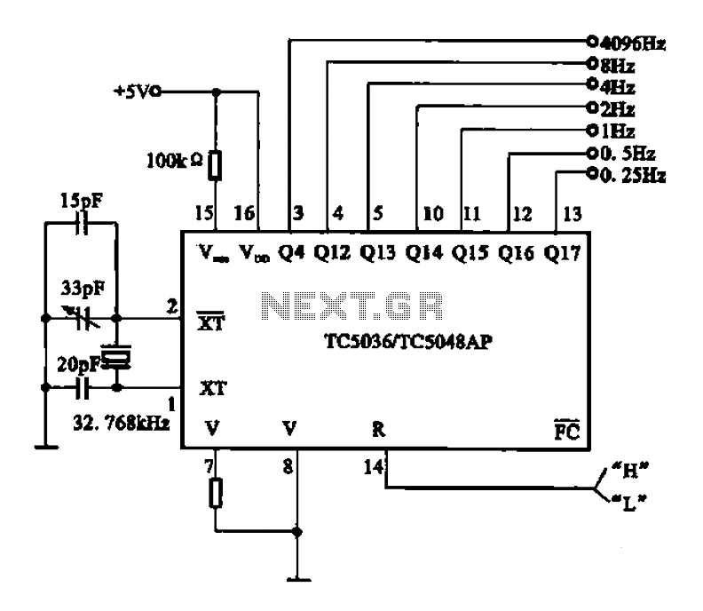
32.768 kHz; In MP3/MP4 devices, mobile phones, laptops, and other digital products, a real-time clock signal generating circuit is utilized, primarily composed of crystal resonators and TC5036/TC5048AP chip oscillators. This setup produces a raw 32.768 kHz crystal oscillator signal,...
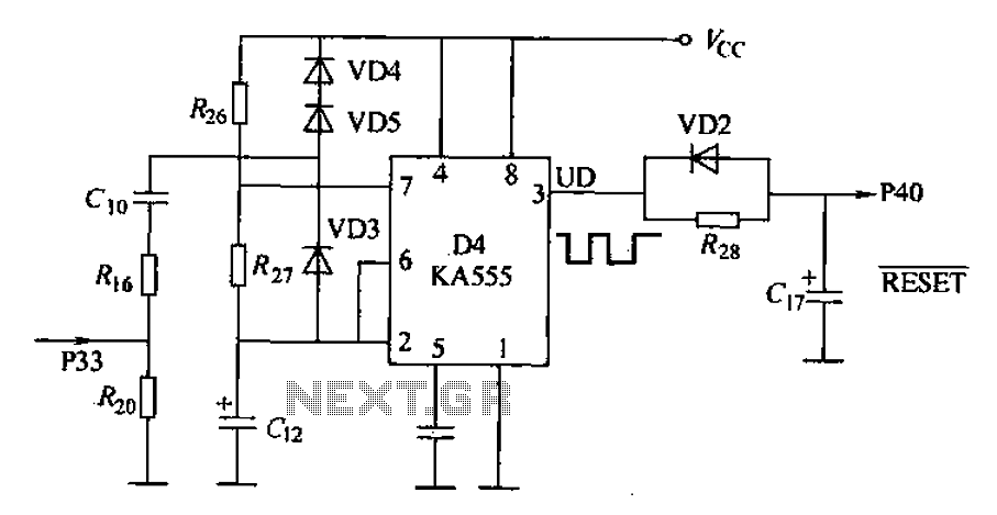
Anti-jamming circuit (watchdog circuit): KA555 interference when analog baseband circuit is shown in Figure 18-14. The KA555 is a hybrid analog/digital integrated circuit. The input signal is connected to specific pins, while the power supply is 5V and the...
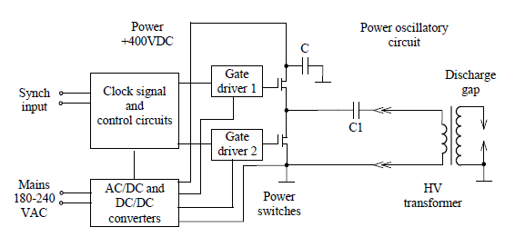
Simulate the electric field within a gas-filled discharge gap generated by a radio frequency voltage generator. The circuit, provided by the experimenters at a distance, is depicted in the accompanying image. The numerical values are as follows: C1 =...

The circuit is designed to regulate a dual power supply that provides +12V and -12V from the AC mains. Such a power supply is an essential tool for an electronic hobbyist's workbench. The schematic of the circuit includes components...
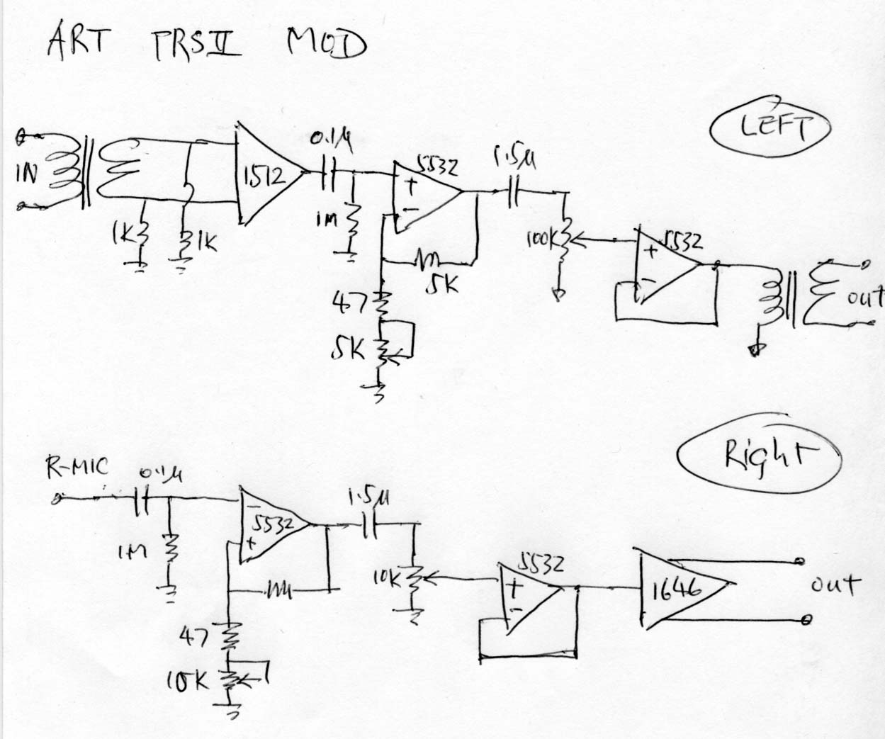
The ART TPS2 is a starved tube microphone preamplifier that utilizes a single 12AX7 tube operating at approximately 50V plate voltage to enhance the sound quality. Initially, the intention was to construct an entirely solid-state preamp, leading to the...