
Temperature control circuit diagram with three-wire serial interface smart temperature sensors DS1620

The described circuit employs a DS1620 temperature sensor, which communicates temperature readings to a microcontroller or logic circuit through its three-wire serial interface. This sensor is capable of providing precise temperature measurements and can be configured for various temperature ranges. The microcontroller processes the data from the DS1620 and determines whether to activate the heater based on the temperature threshold set in the system.
The CD4044 is utilized as an RS flip-flop, which serves as a memory element in the circuit. When the flip-flop is set, it outputs a high signal at Q, which is crucial for controlling the MOSFET. The 2N6659 MOSFET acts as a switch, allowing the flow of current to the small electric heater when it is turned on. The specifications of the 2N6659, including its maximum drain-source voltage of 35V and power dissipation of 6.25W, indicate its suitability for controlling low to medium power loads such as small electric heaters.
This circuit design emphasizes the importance of temperature regulation in heating applications, ensuring that the heater operates only when necessary, thereby enhancing energy efficiency and safety. The combination of the DS1620 sensor, CD4044 flip-flop, and 2N6659 MOSFET creates a reliable and effective temperature control system for small electric heaters. Proper layout and component selection are essential for achieving optimal performance and reliability in this application. As shown in FIG grounds with three-wire serial interface smart temperature sensors DS1620 small electric heater temperature control circuit. When cd4044 type rs flip-flop is set 1, q 1, so 2n6659 tmos fet turned on, power small electric heater on. 2n6659s udso 35V, pd 6.25W.
Related Circuits
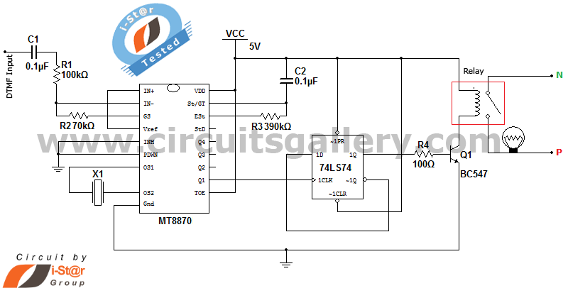
It is possible to control home and office electrical appliances using a mobile phone. This document presents a simple home automation electronic mini project circuit diagram designed for engineering students, allowing the control of electrical appliances without the use...

This LED VU Meter (volume unit) is designed to monitor and display power levels present at the speaker terminals of a stereo audio power amplifier. The levels are represented in ten discrete steps using ten LEDs for each channel,...
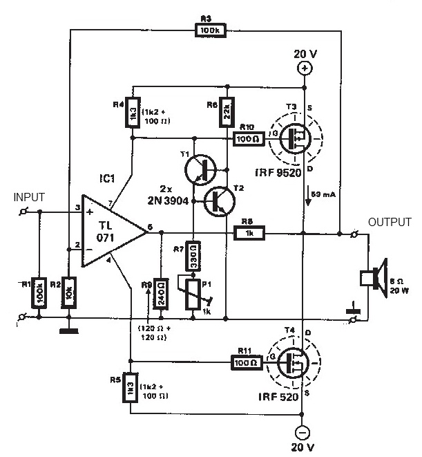
The audio amplifier illustrated in this circuit diagram is a straightforward and efficient audio amplifier circuit based on the TDA1308 integrated class-AB stereo headphone amplifier. This device is manufactured using a 1 mm Complementary Metal Oxide Semiconductor (CMOS) process...
This circuit is designed for use with inductive pick-up elements and dynamic microphones. Most soundcards feature a line input and a separate input for electret (condenser) microphones. To connect an inductive tape recorder head or a dynamic microphone, an...
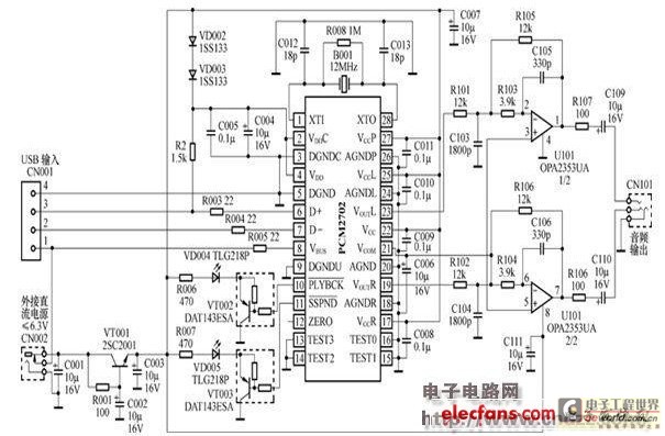
The peripheral circuit is straightforward, consisting of a DAC schematic circuit diagram for a USB interface that utilizes the PCM2702. The output of the circuit can be directly connected to a power amplifier and is capable of driving headphones...

This schematic is directly sourced from the Altera ByteBlaster datasheet or manual, which provides comprehensive details regarding the connector's functionality and pin connections. It is advisable to review the datasheet available on their website or through a search engine...