
dtmf cell phone controlled home appliances automation project

The circuit operates by utilizing the DTMF technology, which encodes the pressed keys into specific frequency pairs. The DTMF decoder IC, such as the M8870, decodes these frequencies into a binary-coded decimal (BCD) output. The configuration of the IC7474 as a toggle flip-flop allows for the detection of key presses, enabling the control of the relay circuit that ultimately operates the electrical appliance.
To implement this circuit, the following components are required: a mobile phone with DTMF capability, a headset jack, a DTMF decoder IC (M8870), a flip-flop IC (7474), a transistor (BC547), a relay, and an electrical bulb. The circuit's design ensures that it can be expanded to control additional appliances by integrating a 4-to-16 decoder IC, which facilitates the management of multiple devices from a single mobile phone interface.
The practical aspect of this project lies in its simplicity and effectiveness, making it an excellent choice for engineering students to understand the principles of home automation and remote control systems. The circuit can be further enhanced by incorporating safety features, such as overcurrent protection and isolation, to ensure reliable operation in various home and office environments.Do you think that you can control your home and office electrical appliances using your cell phone Yes. !you can Here is a simple home controls home automation electronic mini project circuit diagram for engineering students, to control any electrical appliances using mobile phone without using a microcontroller.
This circuit makes use of DTMF (Dual Tone Multi Frequency) technique. We have already posted on What is DTMF and DTMF decoder circuit using M8870 decoder IC. This home appliances control or home automation project also uses the same DTMF decoder circuit section with little modifications to control home and office electrical appliances. Just connect your cell phone headset (headphone) jack to the mobile phone and then mobile will control electrical appliances and electricalequipment through theDTMF key pad of your cell phone.
Here for demonstrating, we are controlling an electrical bulb using this circuit project but you can extend this circuit to control many electrical devices with some modifications using 4G—16 decoder IC. When you press any key on your mobile phone while call is in progress, the other person will hear some tones corresponding to the keys pressed.
These tones are based on the DTMF (Dual Tone Multi Frequency) technology. Data is transmitted as pairs of tones. The receiver detects the valid frequency pair and gives the appropriate BCD code as the output of the DTMF decoder IC. See the figure below. Cut the microphone wire and you will be able to see 4 wires. Among these wires you need only 2 wires- Ground and Right as shown in figure. The signals from the microphone wire are processed by the DTMF decoder IC which generates the equivalent binary sequence as a parallel output of Q1, Q2, Q3, and Q4.
IC7474 is configured as Toggling mode, that is if it gets a clock pulse the output of this IC (Pin 5) sets to high and further clock pulse resets back the IC. (The outputs toggle whenever a key is pressed). When we press and release any of the keys among 1, 3, 5, 7, 9 and *, the DTMF decoder IC generates a high pulse which acts as a clock to our flip flop and sets the output flip flop to high.
The output of flip flop is connected to the relay driver circuit via 100 © resistor; this output energizes the relay coil through BC547 transistor and turns ON the bulb that is connected at the normally open terminal of relay circuit. 🔗 External reference
Related Circuits
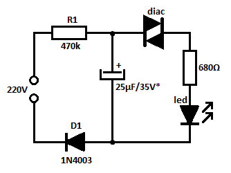
This is likely the simplest concept for generating a flashing light from an LED using alternating current (AC). The circuit provides a straightforward method for flashing one or more LEDs using high-voltage direct current (DC) sourced from mains electricity....
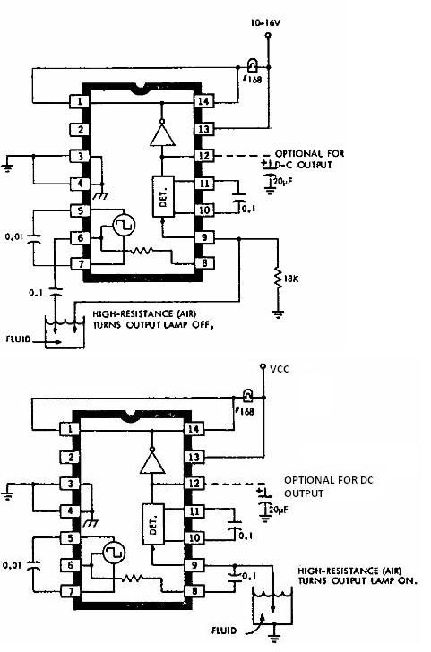
This electronic liquid detector circuit diagram is based on the ULN2429 monolithic bipolar integrated circuit designed for detecting the absence or presence of many different types of liquids. The ULN2429 electronic liquid detector circuit can be used in automotive,...
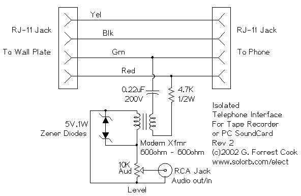
This circuit allows you to record audio from a telephone line into a tape recorder or computer soundcard. Most of the parts for this circuit can be scrounged from an old modem; with some work, it is possible to...
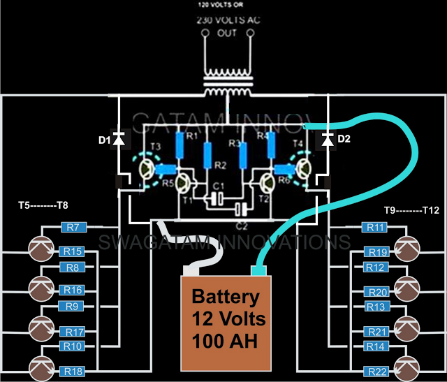
The current design of a power inverter offers an efficiency of approximately 85% and a power output exceeding 200 watts. This document provides a complete circuit schematic and detailed building procedure for a home-built power inverter. While numerous articles...
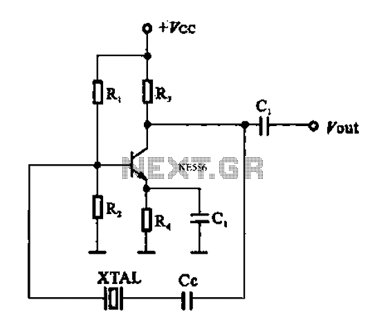
A series resonant circuit utilizing a crystal oscillator is illustrated. The crystal impedance reaches a minimum value at the series resonance frequency, resulting in a significant feedback amount. The crystal tuning capacitor (Cc) can slightly adjust the resonance frequency...
This circuit was inspired by a friend who wanted a reverb for his portable guitar amplifier. I originally tried using NE5532 low noise op-amps for the buffer stages but they were too noisy for the low level circuits so...