
Temperature controlled fan regulator

The fan regulator circuit employs a TRIAC (Triode for Alternating Current) as the main switching component, which allows for control over AC power delivered to the fan. In this design, the NTC (Negative Temperature Coefficient) thermistor (R1) decreases its resistance with increasing temperature, providing a lower resistance path that increases current flow. Conversely, the PTC (Positive Temperature Coefficient) thermistor (R2) increases its resistance with rising temperature, limiting current flow and creating a differential response to temperature changes.
The interaction between R1 and R2 generates a variable voltage that is fed into the gate of the TRIAC. The TRIAC's firing angle is controlled by this voltage, determining the duration for which the TRIAC is conductive during each AC cycle. This results in a proportional adjustment of the average voltage supplied to the fan, effectively controlling its speed.
To enhance performance, the circuit may incorporate additional components such as capacitors for filtering or diodes for protection against reverse polarity. A heat sink may also be employed on the TRIAC to dissipate heat generated during operation, ensuring reliability and longevity of the circuit. Additionally, careful selection of the thermistors' characteristics is crucial to achieve the desired response time and sensitivity to temperature changes, allowing for effective fan speed regulation in various environmental conditions.This fan regulator circuit will automatically control the speed of your fan according to the temperature. Two thermistors (R1 and R2) are used to sense the temperature. The circuit works almost like the published here previously. Here the potentiometer is replaced by the thermistors. When the temperature is increasing the resistance of NTC thermis tor ( R1) decreases and at the same time the resistance of PTC thermistor (R2) increases. At the same time, rate of change of the resistance will be different for R1 and R2. This action is similar to a potentiometer used in a conventional Triac based fan regulator. When the resistance is varied the firing angle of the triac changes and so do the speed of the fan. 🔗 External reference
Related Circuits
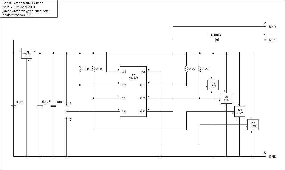
Just a handful of components builds an 8-pin microcontroller based circuit for temperature logging via a serial port; small, fast, and acceptably accurate. More: provides real-time data to your computer via serial port, interfaces up to four DS1820 temperature...

This simple temperature relay circuit can be used to signal a fire or setpoint for temperature monitoring function. You need to adjust P1 so that T1's base. The temperature relay circuit operates by monitoring the temperature in a designated area...
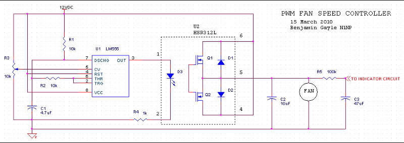
A fan speed controller for computer fans consists of two sections: one for manual speed control and another for automatic temperature-dependent speed control. Additionally, there is a section for a simple LED output indicator. While it is common to...
The circuit is a common three-terminal linear regulator expansion flow circuit. In practical applications, it may encounter some well-considered or lower false failures. 1. Disadvantages of this power supply: 1.1 This power supply is a linear regulator...

If an AC fan has three buttons (as in this case), button 1 is for low speed, button 2 is for half speed, and button 3 is for high speed. A relay can be used to switch between these...
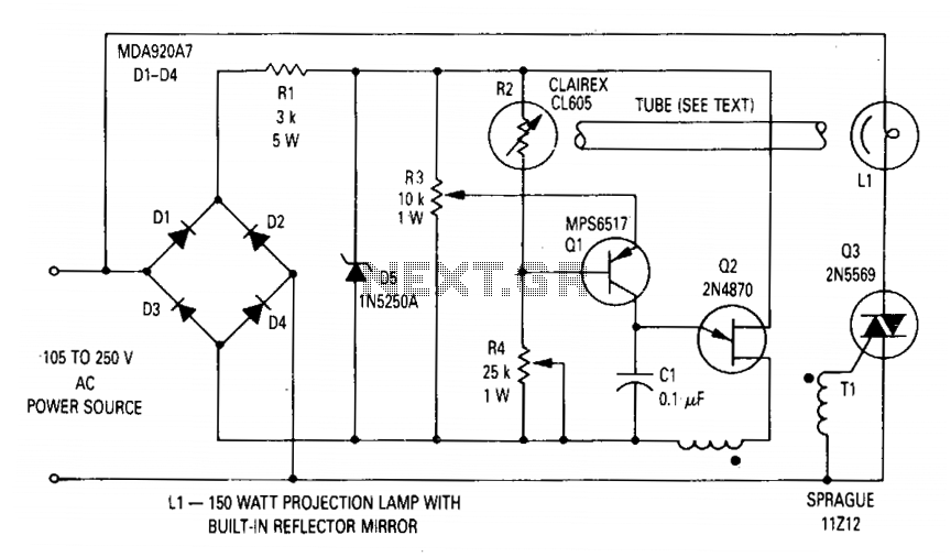
The circuit regulates the RMS output voltage across a load, specifically a projection lamp, to 100 volts ±2% for input voltages ranging from 105 to 250 volts AC. This regulation is achieved by indirectly sensing the light output of...