
fan 220v ac speed control

A comprehensive electronic schematic for the described AC fan speed control circuit can be developed to incorporate the functionalities outlined. The circuit will feature three fixed resistors, each connected in series with a transistor switch. The transistors will be controlled by a microcontroller or logic circuit, allowing for precise selection of the desired fan speed.
The triac will be used for controlling the AC power to the fan, with a diac providing the necessary triggering for the triac. The variable resistor can be replaced with a combination of fixed resistors, allowing for discrete control of the fan speeds. Each transistor will be connected to its respective fixed resistor, and when activated, will effectively change the resistance seen by the triac, thus adjusting the fan speed.
To ensure smooth operation, a small capacitor can be connected in parallel with the variable resistor to filter any noise and provide a stable trigger signal to the triac gate. The PWM signals can be generated by the microcontroller, where the duty cycle can be adjusted based on the selected speed setting.
Additionally, safety considerations should be taken into account by incorporating fuses or circuit breakers to protect the circuit from overcurrent situations. Proper heat dissipation measures for the triac and transistors should also be implemented to prevent overheating during prolonged operation. This design will provide a reliable and efficient means of controlling the speed of an AC fan using modern electronic components.if your AC fan have 3 button (like i have), button 1 (for low speed), button 2 (half speed), and button 3 (high speed), you can use Relay for switch the speed changing that button. But if your AC fan have 3 button (like i have), button 1 (for low speed), button 2 (half speed), and button 3 (high speed), you can use Relay for switch the speed
changing that button. I have built a circuit which works with Relays and my 2 bit instructions for 25%, 50% and 100% but it requires three relays and three AC Fan dimmers (ready made from market). I actually wanted to use Triac because relay logic is old and Relays burn easily and have a very small life as compared to Triac.
in AC, the speed is proportional to amount of energy given to fan/bulb. which is again proportional to the area under the curve of AC voltage. e. g. here i shows a figure where three AC channels are switched at different times. you can see the AC wave delivered to the device is lesser than the original AC (Yellow curve). so the area under the AC curve is different in all cases and hence your o/p voltage varies. there is no PWM remember. Ajay i have seen your Home Automation software and how you use "lwidth" for generating PWM. I want to do similar thing but i need to generate 3 PWM as mentioned in my post above. AC Fan speed is control by a triac + diac + a VARIABLE Resistor that actually (with the help oa small cap) trigger the gate of Tric at various delay (according to the vale of variable RESISTOR) due to that delay tric get ON for that much time only. U break that variable resistor into= three fix resistor and switch them in to series with the help of transistor that will be control by your logic state.
for example. if fan speed is controll fromm full to minimum by 500k resistor= use four 150k fix resistor in series = 600k and across each 150k resistor use (in parallel) a transistor or a opto when a transistor is switched on then 150k resistor is reduce to ~1k and 600k will be reduce to 450k and fan speed will increase. try and inform 🔗 External reference
Related Circuits

PICLink RS232 low-cost development controller with ADC. The PICLink RS232 embedded controller module provides any microcontroller with RS232 communication capabilities. The PICLink RS232 embedded controller is designed to facilitate communication between microcontrollers and RS232 devices, making it an essential component...
There are two types of solar automatic tracking controllers. One type utilizes a Schmitt trigger light control, which consists of a light sensor and a Schmitt trigger or monostable trigger. The second type employs two light sensors and two...
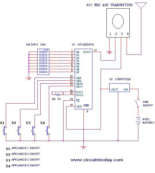
This project outlines a simple remote control system utilizing RF communication without the use of a microcontroller. The remote is designed for various home appliances such as televisions, fans, and lights, providing significant convenience by allowing operation from a...
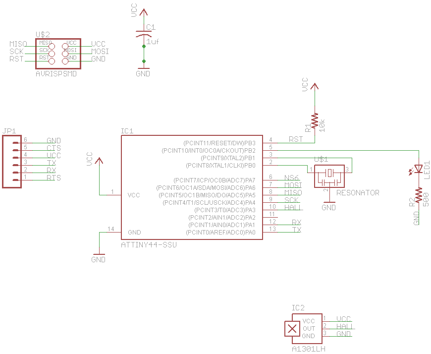
The final project involves cycling rollers that require a method to sense the rotational speed of one of the rollers. Speed sensors on bicycles typically function by detecting a magnet attached to a spoke on one of the wheels...
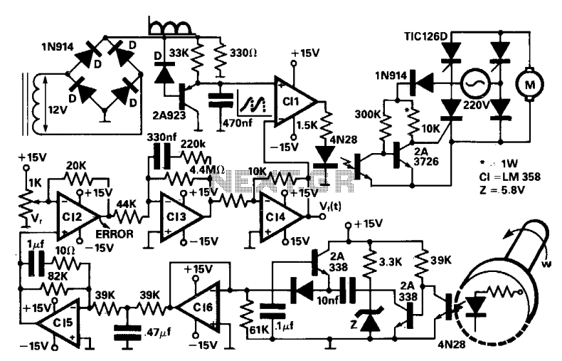
A four thyristor controlled bridge is utilized for operation in two quadrants of the torque-speed characteristics. In the trigger circuits, conventional pulse transformers are substituted with self-biased circuits, which reduce gate power consumption and enhance noise immunity. Electrical isolation...
This is a measurement I did on a FM receiver (MC3372). I have plotted the output DC-bias as a function of the IF (Intermediate Frequency) frequency. At 455kHz you can see that I have 5.5V DC bias. When I...