
Temperature Controller For PC PCB

The temperature controller circuit is designed to maintain optimal operating conditions for personal computers by monitoring and regulating internal temperatures. The LM35 temperature sensor provides a precise voltage output proportional to the temperature, allowing for accurate monitoring. The CA3140 comparator compares the output voltage from the LM35 with a reference voltage set by the VR1 potentiometer. This adjustable reference allows for customization of the cutoff temperature according to user requirements.
When the temperature remains below the set threshold, the comparator outputs a high signal, keeping the triac in the conducting state, which allows current to flow to the PC. This ensures that the computer remains operational during normal conditions. However, once the temperature exceeds 55 degrees Celsius, the comparator's output drops to a low state, which turns off the triac. This action interrupts the power supply to the PC, effectively shutting it down and preventing potential damage from overheating.
The resistors R1 and R2 serve to stabilize the output voltage from the rectifier circuit, ensuring reliable operation of the temperature controller. The ZD1 component, a zener diode rated at 9V and 0.5W, provides additional voltage regulation, maintaining consistent performance across varying input conditions.
This temperature control circuit is particularly beneficial for high-performance PCs that generate significant heat during operation, as it helps to prolong the lifespan of critical components by preventing thermal stress. By integrating this simple yet effective temperature controller, users can safeguard their systems from the adverse effects of overheating, ensuring stable and reliable performance.Our computer may often heated up due to long use or the hot climate, temperature controllers are necessary. You need to do a temperature measurement to ensure that the computer is work within the allowed range.
To reduce pc temperature, here is circuit diagram of a simple temperature controller for your personal computer (PC) based on a temperatur e sensor LM35 and a comparator CA3140. The circuit turns off the PC when the temperature of the computer increases beyond a particular, optimum temperature value. This avoids overheating of some integrated chips (IC) that may not be able to dissipate heat fast enough.
For this pc temperature controller, the cut off temperature is assumed to be 55 degree Celsius. The circuit contains a temperature sensor LM35 and comparator. ( The threshold value of 55 can be adjusted using VR1 potentiometer actually varies the comparator reference voltage). The R1, R2 and ZD1(9V, 0. 5W) used for stabilizing the output of the rectifier. In normal temperature, the comparator produces an error voltage which triggers the triac that give supply to PC (load).
Whenever the PC temperature go beyond the threshold value, the comparator output become low, causes to shut down the triac hence the PC. 🔗 External reference
Related Circuits
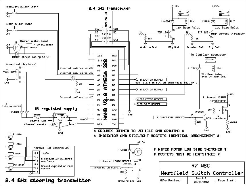
The core of the switch controller is an Arduino Nano microcontroller, which will serve as the interface between the dashboard switches, wireless steering wheel buttons, and the vehicle's lighting, indicators, windscreen wipers, and DigiDash2 GPS stopwatch. This setup facilitates...
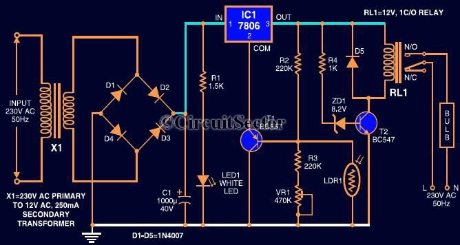
This circuit automates the control of street or porch lights. The automatic lamp controller circuit utilizes a 7806 voltage regulator IC, which can be employed to automate street lights, tube lights, or any other home electrical lighting systems. The...
This project uses only a few of the instructions that come with PicBasic, but serves to show how easy PicBasic really is. It also shows how PicBasic strongly resembles programming the BASIC Stamp. Here we are using the serin...
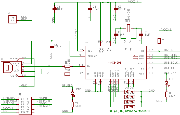
The MAX3420 is a USB peripheral controller chip featuring an SPI bus. This document aims to provide sufficient information for effective utilization of the device in various projects. The MAX3420 simplifies the integration of a USB interface into a...
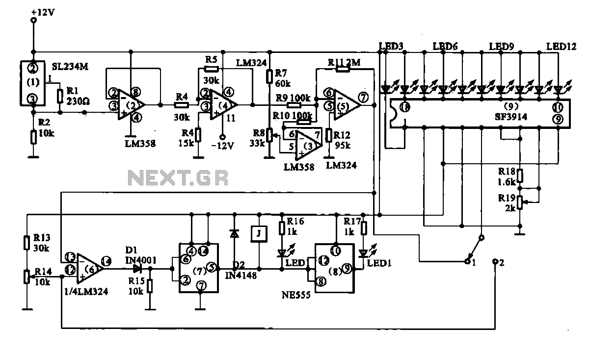
Vegetable greenhouse temperature detection control circuit. The greenhouse temperature detection control circuit is primarily composed of a temperature sensor SL234M, operational amplifiers LM324 and LM358, a dual time base circuit NE555, a relay, and a display driver circuit. The...
The MIC2199 is a synchronous buck switching regulator controller. It features an all N-Channel synchronous architecture and powerful output drivers that enable a maximum output current capability of 20A. The device operates with an input voltage range of 4.5V...