
Implementing A Sewing Machine Controller With An Mc9rs08ka2 Microcontroller

The MIC2199 synchronous buck switching regulator controller is designed to deliver high efficiency and robust performance in various applications, including power management for microcontrollers and other digital devices. The all N-Channel synchronous architecture significantly reduces conduction losses, making it suitable for high current applications. The ability to program the output voltage between 0.8V and 6V provides flexibility for different load requirements, while the wide input voltage range allows compatibility with various power sources.
The 300kHz switching frequency not only enables the use of smaller inductors but also contributes to the overall compactness of the circuit design. The external COMP pin is an essential feature, allowing designers to optimize the transient response by selecting appropriate output capacitors based on the application's specific needs. This adaptability is crucial in ensuring stable operation under varying load conditions.
While the absence of an external soft-start pin may initially seem limiting, the proposed method of implementing soft-start through the use of a capacitor and diode provides an effective solution. By connecting a capacitor (C1) and a 1N4148 diode between the VOUT and FB pins, the output voltage can be gradually ramped up, minimizing inrush current and preventing potential damage to connected components.
The output voltage waveform depicted in Figure 1 serves as a valuable reference for evaluating the performance of the MIC2199 in real-world applications. The observed overshoot and rise time characteristics are critical factors that engineers must consider when designing circuits to ensure reliability and efficiency. Overall, the MIC2199 is a versatile and powerful solution for applications requiring efficient voltage regulation and high output current capabilities.The MIC2199 is a synchronous buck switching Regulator controller. An all N-Channel synchronous architecture and powerful output drivers allow up to a 20A output current ca- pability. The MIC2199 operates from a 4. 5V to a 32V input and CAN be programmed for output voltage from 0. 8V to 6V. The 300kHz switching frequency allows the use of smaller ind uctor and the external COMP pin allows different output capacitor to be used for optimum transient response. To keep the pin count to a bare minimum, the MIC2199 does not offer an external soft-start pin that allow to reduce inrush current by delaying and slowing the output voltage rise time by connecting a capacitor on this pin.
Figure 1 shows the output voltage waveform for a stan- dard MIC2199 circuit that takes about 120 µs and exhibits an output voltage overshoot for VIN = 12V, VOUT = 3. 3V, I LOAD = 0A. Figure 2 shows a simple and inexpensive way of implementing external soft-start on the MIC2199 by using a capacitor, C1 and a Diode 1N4148 between VOUT and FB pins.
🔗 External reference
Related Circuits
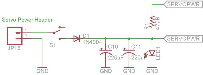
This document explains how to utilize an Arduino to control up to 12 servos simultaneously with minimal jitter. A straightforward serial interface allows for the control of the position of these 12 servo channels. Additionally, it is possible to...
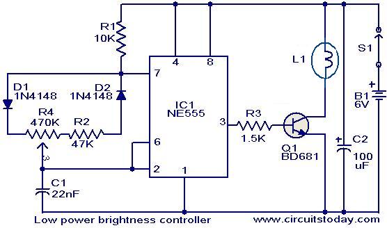
The circuit presented here is designed to control the brightness of low-power incandescent lamps. It utilizes the NE555 integrated circuit, configured as an astable multivibrator with a variable duty cycle. The output from the IC is connected to the...
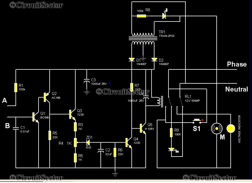
This is an automatic water tank controller designed to manage the operation of a water pump using a 12V 10A relay. When the water level in the tank creates a short circuit between points A and B in the...
PWM is a device that can be utilized as an efficient light dimmer or DC motor speed controller. Function: for a general-purpose device that can... PWM (Pulse Width Modulation) is a versatile technique widely employed in various electronic applications, particularly...
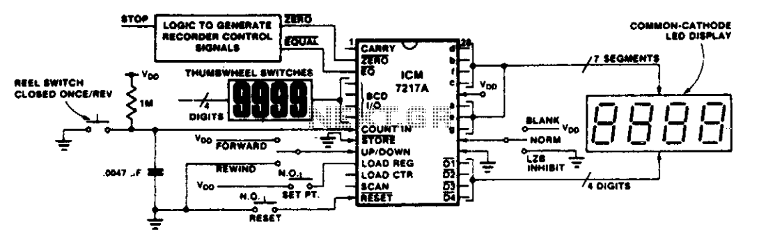
This circuit illustrates various applications of up/down counting for monitoring dimensional position. In the tape recorder application, the LOAD REGISTER, EQUAL, and ZERO outputs are utilized to control the recorder. To ensure the recorder stops at a specific point...
A motor coil requires controllers to adjust its position and speed. A motor driver is necessary to amplify the low output current from a controller to a larger current required by the motor. The following article describes how to...