
PWM DC Power Controller

The described DC power supply controller employs a timer IC, specifically the 7555, to generate a PWM signal that controls the output voltage and current. The PWM signal is a technique used to adjust the average power delivered to the load by varying the width of the pulses in a fixed frequency signal. This approach allows for efficient control of the power supply without significant heat generation, making it suitable for various applications.
The circuit typically consists of several key components: the 7555 timer IC, resistors, capacitors, and possibly transistors or MOSFETs for power amplification. The values of the resistors and capacitors connected to the timer IC determine the frequency and duty cycle of the PWM signal. The duty cycle, defined as the ratio of the time the signal is high to the total time period, directly influences the output voltage. A higher duty cycle results in a higher average voltage delivered to the load, while a lower duty cycle decreases the voltage.
In practical applications, the PWM output from the timer IC may drive a power stage, such as a transistor or a MOSFET, which serves to switch the load on and off rapidly. This switching action allows for fine control over the power delivered to the load while minimizing energy loss. Additionally, feedback mechanisms may be incorporated into the design to stabilize the output voltage and current, enhancing the performance of the power supply controller.
Overall, this PWM-controlled DC power supply design is characterized by its simplicity, efficiency, and versatility, making it suitable for various electronic applications requiring stable and adjustable power sources.This DC power supply controller is controlled by pulse width modulation PWM, generated by the circuit around timer IC2 7555 according to the formula: Duty.. 🔗 External reference
Related Circuits
Class-A is ideal for this application, since headphones are such an intimate way of listening. An amplifier for 'phones should be as clean and free from crossover distortion as possible, and must also be quiet. A background of hiss...
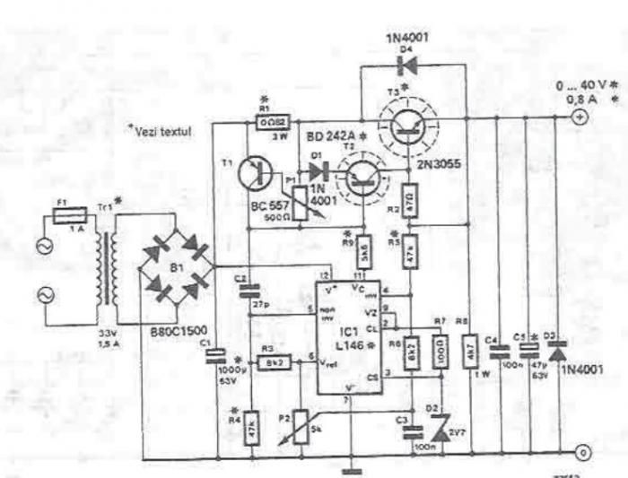
An adjustable laboratory power supply capable of providing an output voltage range from 0 to 60 volts can be constructed using the provided circuit diagram. This power supply can utilize the LM723 chip for lower voltage applications or, for...
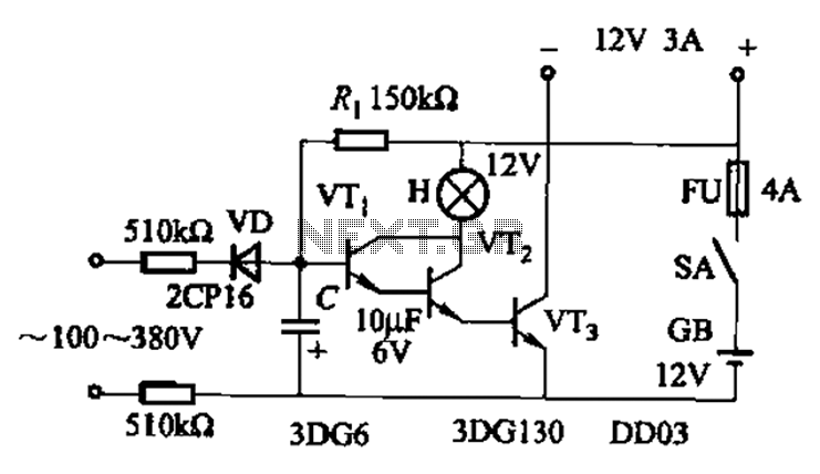
An AC-DC power supply without a power switching circuit is typically utilized for lighting load circuits. Once the power grid is restored, the standby power supply automatically switches on. An automatic switching circuit using a transistor is implemented, with...
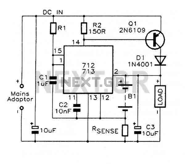
The MAX712 and MAX713 are nickel cadmium (Ni-Cd) battery fast charge controllers that facilitate the rapid charging of batteries from a DC source, which must be at least 1V higher than the maximum battery voltage. These controllers can charge...
Circuit diagram of marine TV dish. Circuit diagram of marine TV dish, circuit diagram of marine TV dish, 12V DC to 120V AC inverter circuit diagram PDF, 12V DC to 120V AC inverter circuit diagram PDF. The circuit diagram for...
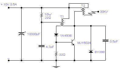
Easy to build, this high voltage generator is capable of generating up to 50KV but the breakdown voltage of the coil limits the voltage to a value somewhat lower. T2 is the ignition coil of a car and also...