
Temperature Conversion circuit

The Excelitas TPS 1T 0134 OAA060 thermopile sensor represents a significant advancement in thermal detection technology, integrating a built-in operational amplifier to enhance its performance. The self-contained nature of this module simplifies integration into various applications, particularly where accurate temperature measurements are crucial. The sensor's ability to convert thermal radiation into a voltage output facilitates its use in a range of environments, with the pre-calibrated options providing immediate usability for temperature readings.
In practical applications, the selection of an appropriate power supply is critical. The recommended 78L05 voltage regulator, paired with a standard 9-V battery, ensures that the sensor operates within its specified voltage range, thereby maintaining accuracy and reliability. The operational characteristics of the sensor can be further optimized by utilizing high-quality resistors in the voltage divider circuit, ensuring that the output remains stable and within the input limits of connected data loggers.
The implementation of a unit-gain non-inverting amplifier serves to buffer the output from the A2TPMI, providing the necessary impedance matching to the data logger. This configuration not only protects the sensor from potential loading effects but also enhances the fidelity of the temperature readings. Calibration procedures, involving direct voltage measurements, are essential to establish a precise correlation between the sensor output and the amplified signal, allowing for accurate temperature determinations in various applications.
Overall, the Excelitas TPS 1T 0134 OAA060 thermopile sensor, with its robust design and integrated features, presents a versatile solution for thermal measurement needs across diverse fields, including environmental monitoring, industrial applications, and research initiatives.The Excelitas TPS 1T 0134 OAA060 thermopile sensor is a self-contained module with a built-in op amp. (We use the A2TPMI 334 OAA 60 designation in this document because that was the PerkinElmer part number when we purchased them.
Since then, PerkinElmer`s optoelectronics division has been sold to Excelitas ( and online searches will still bring up references to this device under the PerkinElmer name and part number. The TPS sensor is described by Excelitas as a "recent upgrade" to the TPMI sensors. It is possible that specifications for the TPS sensor ” and, in particular, the equation for converting voltage to temperature ” might be slightly different from the A2TPMI. ) These detectors sense thermal radiation, with spectral response as shown in the graph below. The units come in a variety of configurations, including units that are pre-calibrated for converting voltage to temperatures in °C.
The AT2PMI 334 OAA060 version produces a voltage output in the range of 0-4. 5 V, corresponding to a temperature range from -27 °C to 60°C. (Only the most extreme polar regions are likely to lie outside this range!) It is easy to check out the operation of an A2TPMI with a multimeter. It requires only a regulated +5V power supply, which can easily be provided with an IC voltage regulator (78L05) and a 9-V battery.
The circuit doesn`t require much power and even a carbon a 9-V battery (sometimes referred to as "heavy duty") widely available at two-for-$1 at dollar stores will last for a couple of days of continuous operation. Because of the chopper-stabilized op amp used in this device, there is a small high-frequency signal on the output, but it should be negligible for this application.
There are some potential problems using this device with a data logger. For most of our projects, we use 12-bit-resolution HOBO U-12 series data loggers. These loggers have an input impedance of only 10 k ©, but, the A2TPMI requires a minimum resistive load of 50 k ©. Also, the A2TPMI voltage output exceeds 2. 5 V for temperatures above 30 °C ” a surface temperature value that is often exceeded. The solution is to combine a passive voltage divider with a unit-gain non-inverting amplifier. Such a circuit can provide the A2TPMI with an acceptably high resistive loading. An op-amp-based unit-gain amplifier has a very high input impedance (so that the load on the voltage divider can be neglected) and a very low output impedance.
Such a circuit provides an appropriate interface between the AT2PMI and the U-12 logger. If the voltage is divided in half, it will never exceed the 0 ”2. 5 V range of the U-12 logger. This requires two equal resistors whose total value (R1 + R2) is at least 50k ©hm. If high-precision resistors are used, then the output from the unit-gain amplifier is just multiplied by 2 to do the temperature calculation shown above. If only 5% carbon film resistors are available, it is possible to test several samples to find two with very close to the same value.
It would also be possible to use a variable resistor, a "trim pot, " to adjust the divider so the output from the unit-gain op amp is exactly half the output from the A2TPMI. In any case, units should be calibrated by measuring the output voltage directly from the A2TPMI and the comparing it to the output from the op amp, to determine the precise relationship between the sensor output and the amplified output voltage.
A circuit diagram is shown below. The op amp should be a high-quality low-noise device. We typically use the LTC1050 for these applications, although there are other pin-compatible choices. (The ubiquitous 747 op amp does not qualify as a "low-noise" alternative, even though it is pin-compatible.
) Because this is such a low-power circuit, A 78L05 5-V regulator in a TO-092 housing is the appropriate choice. The pins on the A2TPMI are fragile, and it might be a good idea to secure at least one of the unused pin
🔗 External reference
Related Circuits
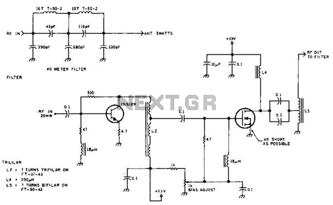
The circuit illustrated is designed to generate up to 5 watts of RF output in the 40-meter (7 MHz) amateur band. The coils depicted are wound on toroidal cores from Armdon Associates Inc., with part numbers provided in the...

This document illustrates the configuration of the high-precision, high-impedance OPA2111 amplifier. The total voltage circuit is designed for a magnification of Av = 10 (1 + 2R2 / R1), achieving a total gain of 1000 times. A gain stage...
The circuit for the power amplifier has a power output of up to 1500W RMS and is commonly utilized in outdoor sound systems. The final image displays a series of power amplifiers that utilize 10 sets of power transistors....

This is a circuit known as a Wien bridge oscillator circuit. The circuit features both positive and negative feedback loops and operates under the control of an operational amplifier (op-amp). The oscillation frequency is determined by the RC time...
This amplifier is designed to be self-contained within a compact loudspeaker enclosure. It can be powered by devices such as Walkmans, Mini Discs, iPods, CD players, computers, and other devices equipped with line or headphone outputs. Typically, two units...
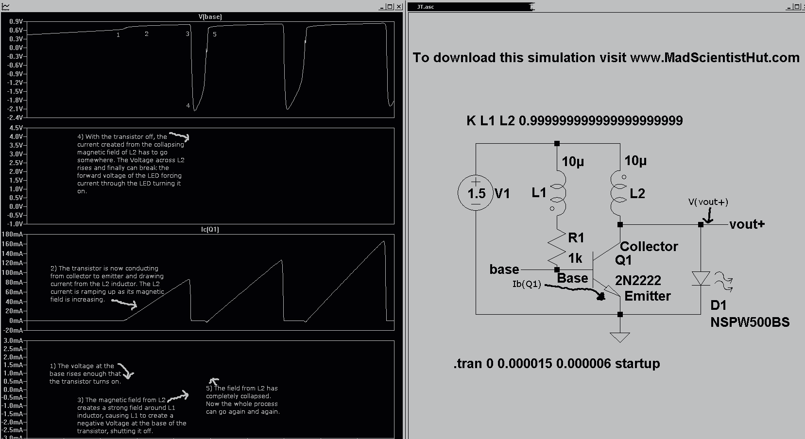
Introducing the Cree 1 Watt LED High Power Joule Thief Kit. Joule Thief Simulation II Graph and Schematic. The Cree 1 Watt LED High Power Joule Thief Kit is designed to demonstrate the principles of energy harvesting and efficient power...