
Temperature Fan Controller

This circuit is designed to provide precise control of a fan based on temperature readings, utilizing a simple yet effective configuration. The core of the design is a differential amplifier, specifically the 741 op-amp, which compares the voltage levels derived from the temperature sensor made of three 1N4148 diodes. These diodes, known for their reliability and availability, are arranged in parallel to enhance sensitivity to temperature variations.
The operational principle hinges on the differential inputs of the op-amp. Pin 2 (non-inverting input) receives a voltage that corresponds to the temperature sensed through the diodes, while pin 3 (inverting input) is set to a reference voltage via resistor R7 (10K). The output from pin 6 of the op-amp will provide a high signal when the temperature exceeds a certain threshold, which in turn activates the connected transistors.
Transistor Q1 acts as a switch controlled by the op-amp output. When pin 2's voltage surpasses that of pin 3, Q1 is activated, allowing current to flow to transistor Q2. This action turns on the fan, which is powered by a 12V supply, ensuring that the fan operates only when necessary. The inclusion of resistor R9 provides feedback to the op-amp, stabilizing the circuit and improving response time.
For practical implementation, the temperature sensor should be encased in a waterproof housing to protect it from environmental factors, particularly in applications such as water baths. The design is limited to DC fans, necessitating careful selection to ensure compatibility with the circuit's specifications. The versatility of the circuit allows it to be adapted for various fan sizes, with adjustments made primarily through the selection of the appropriate resistor values, particularly R6.
Overall, this circuit exemplifies an efficient approach to temperature-controlled fan operation, leveraging common electronic components to achieve reliable performance in temperature regulation applications.This circuit controls very accurately a fan of any size. Just adjust the associated resistors for a different type like the R6 resistor of 100 ohm, 2 watt type and you're all set. The above circuit diagram is for a small 12 volt fan, the size and type determined by the user. Temperature is sampled via the 1N4148 diodes and presented at pins 2 and 3 of the differential type 741 op-amp.
R7 (10K) is used to create a voltage difference between the inverted and non-inverted input pins 2 and 3 of the 741. All signals presented at pin 2 will be inverted on the output pin 6. Obviously then, the input pins are very important. When pin 2 goes more positive than pin 3, the output pin 6 of the 741 goes high and forward biasing the base of transistor Q1, which switches on transistor Q2 and the Led and puts 12V on the output pins for the fan. R9 functions as a feedback for the 741. Only DC type fans can be used with this schematic diagram without further modifications. The temperature sensor is made up of three easily available 1N4148 signal diodes mounted in parallel.
Mount them in a thin aluminum, or plastic tube (depending on your application) and silicon the end of the tube to make this temperature sensor water-proof. As an additional note, I have seen this type of temperature sensor, with the diodes either in parallel or series and either 1 or more diodes, in all sorts of laboratory equipment like hot water baths and others.
The water bath temperature setting ranged from room temperature to about 100° Celsius. Keep in mind that using the 1N4148 diode as a temperature sensor is very accurate when used within the specifications of the 1N4148. 🔗 External reference
Related Circuits
Understanding how to program the PIC microcontroller in theory is beneficial; however, practical learning occurs when the code is executed on a PIC within a circuit. One can either construct a new circuit for each test or utilize a...
The controller circuit illustrated in Figure 15-24 consists of a switch-type Hall integrated circuit DN838 and an astable multivibrator, which is based on the 555 timer IC. This circuit is suitable for various applications, including automatic door opening, delay...
No description available. More: Q1, Q2: Standard-Transistoren D1: SB130 Q3: RFD 15 N 05 IC1A: CD4011B (if SMD) IC1B: detto The provided components suggest a basic electronic circuit that incorporates both transistors and integrated circuits, along with a diode. The circuit...

H-Bridge circuit utilizing transistors for the bidirectional control of a DC motor. Integrated circuits (ICs) containing H-Bridges are employed to simplify the drive circuit. The L293D is a dual H-Bridge motor driver, allowing for the control of two DC...
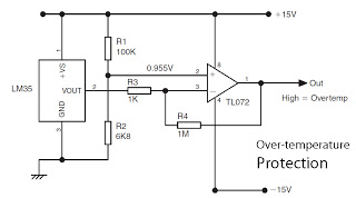
This is a basic overview of the LM35 temperature sensor, which is interfaced with an operational amplifier (op-amp) to boost its output. The LM35 provides a high output voltage when it detects high temperatures. The output can be utilized...
There are two types of solar automatic tracking controllers. One type utilizes a Schmitt trigger light control, which consists of a light sensor and a Schmitt trigger or monostable trigger. The second type employs two light sensors and two...