
Touch sensor switch using inverters

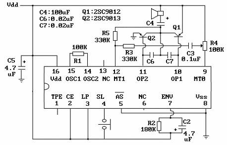
The circuit employs two inverters, N1 and N2, which are essential for signal processing. The oscillator, composed of N3 and N4, generates a continuous 1 MHz square wave signal that serves as the input for the first inverter, N1. The touch sensor is designed to detect changes in capacitance when a hand approaches, effectively altering the input signal at N1. This change is crucial as it determines the logical state at the output of N2.
When the sensor is inactive, the signal from the oscillator maintains a logical high state at N1, which in turn keeps N2 outputting a logical '1'. The introduction of a hand near the sensor modifies the capacitance, creating a capacitive coupling to ground. This coupling reduces the input voltage at N1, leading to a drop in the output state of N2 to logical '0'.
Upon removing the hand from the sensor, capacitor C4 begins to charge through diode D1, allowing for a brief delay before the output of N2 returns to logical '1'. This delay is significant for applications requiring a momentary response to touch, providing a clear indication that the sensor was activated. The diode D1 plays a crucial role in ensuring that the charge does not discharge too quickly, thereby maintaining the output state for a short duration after the touch is released.
Overall, this touch sensor switch circuit is a practical example of how capacitive sensing can be implemented using basic electronic components, offering a reliable solution for touch-sensitive applications.This touch sensor switch can is designed using inverters (N1, N2)and some common electronic components. In standby state at the entrances of N1 there is a signal produced by oscillator N3/N4. At the touch sensor hand capacity forms a bridge to the ground for the 1MHz signal so that the voltage signal at the entrance of N1 decreases more (at the ex
it of N2 is logical 1). After the release of contact, a signal charge C4 through D1 Mhz, so the output of N2 is 0 logic after short time. 🔗 External reference
Related Circuits
The core component of this circuit is the UM3481 integrated circuit (IC), which operates with a 1.5-volt battery. It is suitable for applications such as electronic doorbells, toys, melody clocks, and music boxes. The UM3481 is engineered to play...
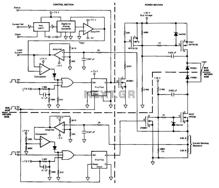
This circuit facilitates on/off switching, soft starting, current monitoring, current tripping, and overcurrent protection for a 30 Vdc power supply, accommodating normal load currents of up to 2 A. The switch is activated by an "on" command pulse and...
This is a 220V touch switch circuit. This circuit functions as a switch that turns off and on the electronic device connected to the 220V home supply. The 220V touch switch circuit is designed to control the operation of electrical...
This circuit is a simple 12V DC to 220V AC inverter that produces an AC output at line frequency, specifically 220V AC, or other voltages by selecting transformer T1. The 555 integrated circuit (IC) is configured as a low-frequency...
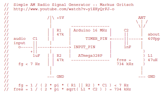
Markus constructed a software AM radio transmitter utilizing an Arduino. The audio signal is supplied to the ADC input via a decoupling capacitor. A PWM output pin directly controls a capacitor-inductor circuit connected to an antenna. The schematic and...
As with the Electronic sel. 8 we also have here a circuit with a choice of 8 different sources. The difference is that only two of the switches are used and the movement of commands is Up-Down in series....