Digital Temperature Controller

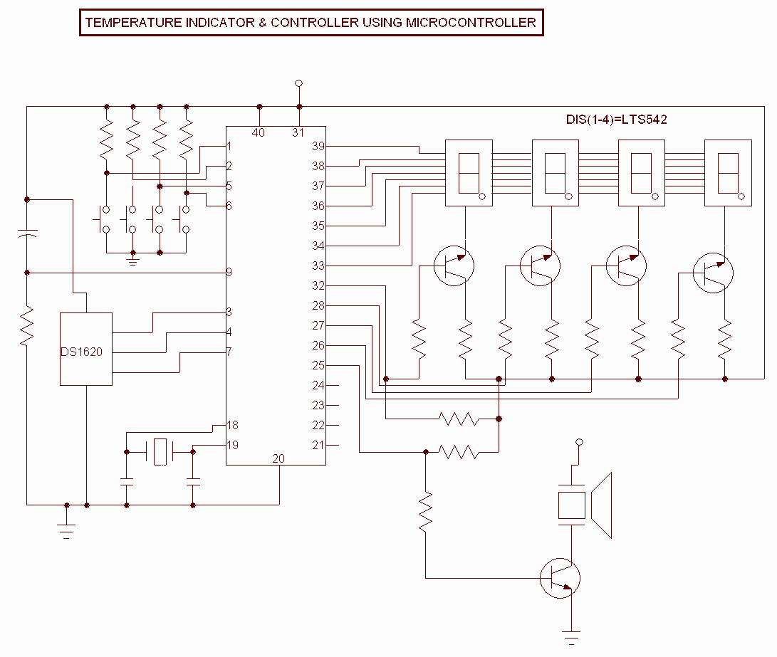
This Project is used to indicate the temperature and it is also used as controller. The system will get the temperature from the IC and it will display the temperature over the seven segment display and this temperature was compared with the value stored by the user and if the Room temperature goes beyond the Preset temperature then an alarm is switched ON until the stop switch is pressed. The System is fully controlled by the microcontroller AT89s52. More: It is a popular 8 bit microcontroller. The circuit consists of four switches, in which two buttons are used to increment and decrement the temperature value and the next button is to start the Thermostat function and the other button is used to stop the t
This project employs a temperature monitoring and control system utilizing the AT89S52 microcontroller, a widely used 8-bit microcontroller known for its reliability and ease of programming. The primary function of the circuit is to monitor ambient temperature, compare it against a user-defined preset, and activate an alarm if the temperature exceeds this threshold.
The system gathers temperature data from a temperature sensor, which is interfaced with the microcontroller. The output from the sensor is processed by the AT89S52, which then drives a seven-segment display to visually represent the current temperature. The display allows users to easily monitor temperature changes in real time.
To set the desired temperature threshold, the circuit incorporates four switches. Two of these buttons are designated for incrementing and decrementing the preset temperature value, enabling users to adjust their desired temperature easily. The third switch initiates the thermostat function, allowing the system to start monitoring and controlling the temperature based on the set point. The fourth switch serves as a stop function, which deactivates the alarm once it has been triggered.
When the monitored temperature exceeds the preset limit, the microcontroller activates an alarm system, alerting users to the temperature anomaly. This alarm will continue to sound until the stop switch is pressed, ensuring that users are made aware of any temperature fluctuations that may require attention.
The circuit design must include appropriate power supply considerations for the microcontroller and the temperature sensor, as well as necessary pull-up resistors for the switches to ensure reliable operation. Additionally, careful attention should be given to the layout of the circuit to minimize noise and ensure accurate temperature readings. Overall, this project provides a robust solution for temperature monitoring and control, suitable for various applications in both residential and industrial environments.This Project is used to indicate the temperature and it is also used as controller. The system will get the temperature from the IC and it will display the temperature over the seven segment display and this temperature was compared with the value stored by the user and if the Room temperature goes beyond the Preset temperature then an alarm is switched ON until the stop switch is pressed. The System is fully controlled by the microcontroller AT89s52. It is a popular 8 bit microcontroller. The circuit consists of four switches, in which two buttons are used to increment and decrement the temperature value and the next button is to start the Thermostat function and the other button is used to stop the t 🔗 External reference


