
temperature stable oscillator

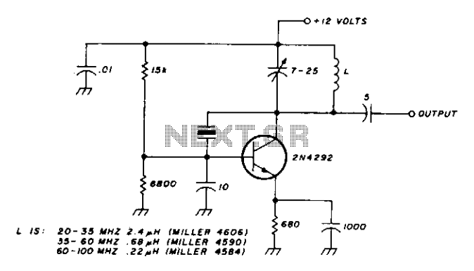
The Colpitts oscillator circuit is a type of electronic oscillator that generates sinusoidal waveforms. It is characterized by its use of a tank circuit, which typically consists of an inductor and two capacitors, to determine the oscillation frequency. In this configuration, the feedback loop is crucial for maintaining oscillation. The feedback is provided from the collector of the transistor through the tank circuit back to the emitter, ensuring that the oscillation is sustained.
The frequency of oscillation (f) can be calculated using the formula:
\[ f = \frac{1}{2\pi\sqrt{L \cdot C}} \]
where L is the inductance and C is the equivalent capacitance of the capacitors in the tank circuit. In this case, the values provided (L1 = 10 mH, C1 = 3500 pF, and C2 = 1500 pF) can be used to find the oscillation frequency. The effective capacitance (C) in parallel can be calculated as:
\[ C = C1 + C2 = 3500 \, \text{pF} + 1500 \, \text{pF} = 5000 \, \text{pF} \]
Substituting the values into the frequency formula yields:
\[ f = \frac{1}{2\pi\sqrt{10 \times 10^{-3} \cdot 5 \times 10^{-6}}} \]
This calculation confirms the operational frequency of 50 kHz.
Potentiometer R3 is employed to control the output level, allowing for fine-tuning of the amplitude of the output signal. The adjustment of resistor R1 enables the biasing of the transistor's base, which is essential for optimizing the performance of the oscillator and achieving a maximum amplitude output.
The low harmonic distortion associated with this oscillator design makes it suitable for applications requiring high fidelity in signal generation. The temperature range of operation further enhances the versatility of the Colpitts oscillator in various environments, making it an effective choice for both laboratory and practical applications in signal processing and communications.The Colpitis sinusoidal oscillator provides stable output amplitude and frequency from 0°F to +150°F. In addition, output amplitude is large and harmonic distortion is low. Oscillation is sustained by feedback from the collector tank circuit to the emitter. The oscillator's frequency is determined by: Potentiometer R3 is an output level control. Control Rl may be used to adjust base bias for maximum-amplitude output. The circuit was operated at 50 kHz with LI = lOmH, Cl = 3500 pF, and C2 = 1500 pF.
Related Circuits
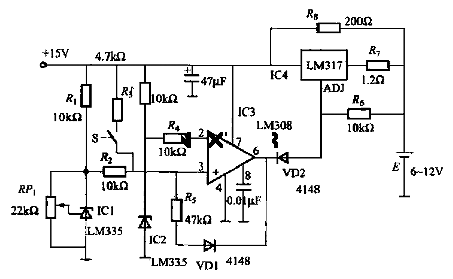
When fast charging a nickel-cadmium battery, the temperature control circuit, as illustrated in the accompanying figure, is designed to monitor the battery temperature to regulate the charging current. The circuit consists of Icl to IC3, which forms the temperature...
This chapter discusses the operation and circuitry of transistor oscillators, which can be categorized into two types: feedback (similar to vacuum tube oscillators) and negative-resistance (current multiplying). Transistor oscillators can generate sine waves using various operational modes, including some...
This oscillator is designed for overtone crystals in the 20-100 MHz range, operating in the third and fifth mode. The operating frequency is determined by the tuned circuit. The oscillator circuit is specifically tailored to utilize overtone crystals, which are...
Design a 32kHz wide supply range oscillator with a low-power comparator, a reference, and crystal oscillator. The circuit design involves creating a 32kHz oscillator that operates efficiently across a wide supply voltage range. The core components include a low-power comparator,...
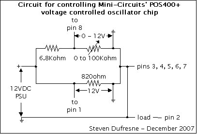
This is a UHF oscillator circuit designed to utilize the Mini-Circuits POS-400+ voltage-controlled oscillator chip. By applying a voltage between 0 to 12V on pin 8, it produces a sine wave output ranging from 200MHz to 380MHz on pin...
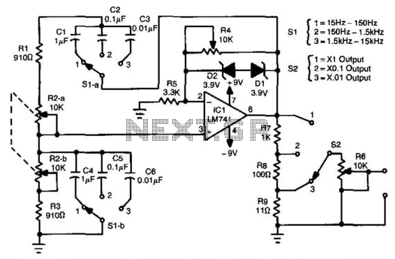
In this circuit, an LM741 operational amplifier drives a Wien-bridge network utilizing two zener diodes as an amplitude limiter. Range selection is performed by a switch that selects between capacitors (C1 through C6), while tuning is achieved using a...