
Asymmetric third order Butterworth active crossover network circuit diagram

The asymmetric third-order Butterworth active crossover network is a sophisticated circuit designed to split an audio signal into two separate frequency bands, typically for use in multi-way speaker systems. This type of crossover employs active components, such as operational amplifiers (op-amps), to achieve a precise frequency response and a smooth transition between the low-pass and high-pass outputs.
In this circuit, the Butterworth filter design is chosen for its maximally flat frequency response within the passband, ensuring minimal signal distortion. The third-order configuration provides a steeper roll-off rate of 18 dB per octave, which enhances the separation between the audio bands, thereby improving overall sound quality.
The circuit typically consists of two main sections: the low-pass filter and the high-pass filter. Each section utilizes multiple op-amps configured in a feedback arrangement to achieve the desired filter characteristics. The cutoff frequency, where the signal begins to attenuate, is determined by the values of resistors and capacitors used in the circuit.
To implement an asymmetric design, the component values can be adjusted to create differing slopes or cutoff frequencies for the low-pass and high-pass sections, allowing for tailored audio performance based on specific speaker characteristics or user preferences.
Power supply considerations are essential for active crossover networks; typically, a dual power supply is employed to provide the necessary positive and negative voltage rails for the op-amps. Additionally, careful attention must be paid to grounding and layout to minimize noise and interference, ensuring high-fidelity audio output.
In summary, the asymmetric third-order Butterworth active crossover network is an advanced circuit that provides effective frequency separation and high-quality audio performance, making it a valuable component in professional audio systems. Asymmetric third order Butterworth active crossover network circuit diagram as follows:
Related Circuits
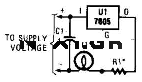
A 7805 can be configured as a constant-current regulator to function as an inrush current limiter. Resistor R1 will maintain a voltage of 5 V across it at all times, resulting in a total current through R1 of 5...
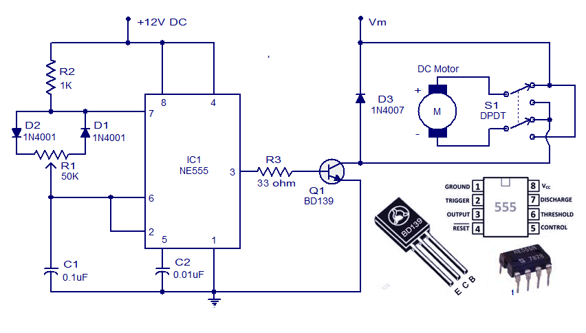
This weblog discusses electronic circuit schematics, PCB design, DIY kits, and electronic project diagrams. A simple DC motor controller circuit utilizing the NE555 timer is presented. Several DC motor speed control circuits are explored, with this being the first...
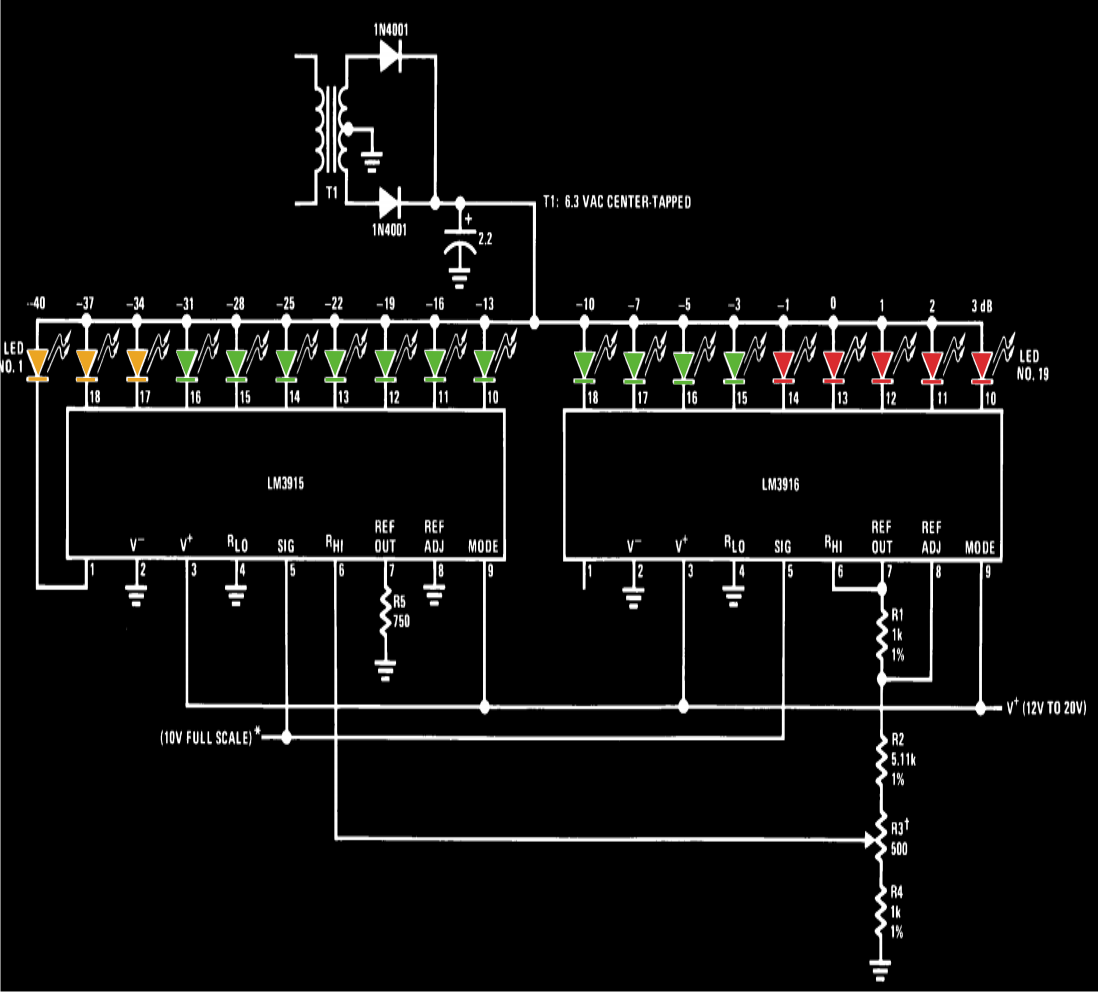
A VU meter, or volume unit meter, is a device used to indicate the music volume output from an amplifier or loudspeaker system. It can also be viewed as a device for displaying the PMPO (Peak Music Power Output)...
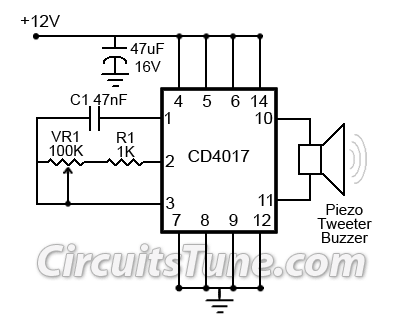
This is a simple ultrasonic mosquito repeller circuit diagram. The circuit is designed based on the theory that pests like mosquitoes can be repelled by ultrasonic frequencies ranging from 20 kHz to 25 kHz. This ultrasonic mosquito repeller circuit...
This circuit is designed to operate an electric strike or an electromagnetic lock on a door. It does not control the door's opening or closing but rather activates a small electromagnetic strike that unlocks the door. The opener features...
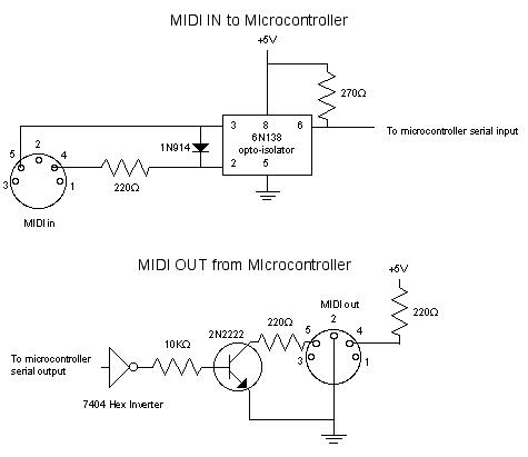
MIDI, or Musical Instrument Digital Interface, is a specification for a communications protocol between digital synthesizers and other digital music devices. It was developed to be as simple and general as possible, providing synthesizer manufacturers with significant flexibility while...