
Infrared Alarm Barrier Circuit

The infrared alarm barrier system is characterized by its simplicity and effectiveness in providing security through motion detection. The design incorporates a transmitter and receiver pair that communicate via modulated infrared light, ensuring reliable operation even in varying environmental conditions. The use of the 555 timer ICs allows for precise control over the modulation frequencies, enhancing the system's sensitivity and response time.
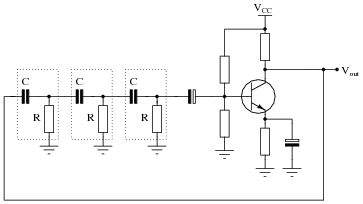
The transmitter circuit begins with the TLC555 configured as an astable multivibrator, generating the 300 Hz pulse. This pulse drives the second 555 timer configured to produce a 36 kHz carrier frequency. The IRED is driven by a transistor, which amplifies the current to ensure that the infrared beam can cover the required distance. The modulation technique employed here is essential for optimizing the performance of the infrared sensors, as it allows them to better differentiate between the transmitted signal and ambient infrared noise.
In the receiver circuit, the incoming infrared signal is processed by another TLC555 timer configured to detect changes in the signal level. The low-frequency rectifier formed by D1 and C2 is crucial for filtering out the modulation frequency, allowing the receiver to respond only when the beam is interrupted. When a person passes through the beam, the interruption triggers the oscillator, which activates the buzzer, providing an audible alert.
Overall, this infrared alarm barrier system is an effective solution for security applications, offering a straightforward yet reliable method for detecting unauthorized access through monitored areas. Its design can be easily adapted to various settings, making it a versatile choice for both residential and commercial installations.This infrared alarm barrier can be used to detect persons passing through doorways, corridors and small gates. The transmitter emits a beam of infrared light which is invisible to the human eye. The buzzer at the output of the receiver is activated when the light beam is interrupted by a person passing through it.
The transmitter and receiver circ uits of the infrared alarm system shown here have been designed for a range of several meters, almost independent of ambient light conditions. Only in the rare case of the receiver sensor being exposed to bright, direct sunlight, some screening measures have to be added.
The transmitter does not emit a continuous infrared signal, Rather, it is modulated, that is, the 36-kHz carrier used to pulse the IRED (infrared emitting diode) on and off is itself switched on an off at a rate of about 300 Hz. The reason for doing so is that most infrared sensors, including the ones suggested in the diagram do not respond very well to continuous incidence of infrared light.
Switching the IR source off, even for a small period, allows IR detectors to recuperate`, and so optimise their ability to minimize the response to ambient light. The transmitter consists of two oscillators built around the ubiquitous 555 IC. Here, the current-saving CMOS version TLC555 (or 7555) is used. Alternatively, the two 555`s may be replaced by a single TLC556 (or 7556). IC1 is the 300-Hz generator, IC2, the 36-kHz source. The IRED type LD274 is pulsed at a relatively high peak current via driver transistor T1. If in your application the distance covered by the IR beam is relatively short, the value of resistor R5 may be increased to save on current consumption.
Preset P1 is adjusted for a carrier frequency of 36 kHz exactly (failing test equipment, adjust it for optimum range). The receiver is equally simple and also based on a CMOS 555. As long as the sensor picks up infrared light from the transmitter, the reset input of the 555 IC is held low and the buzzer is silent.
Components D1 and C2 act as a low-frequency rectifier to cancel the effect of the 300-Hz modulation on the transmitter signal. When the infrared light beam is interrupted, the oscillator built around the 555 is enabled and starts to produce a warning tone.
Finally, the test values indicated in the infrared barrier alarm circuit diagram are average dc levels measured with a DVM, under light/no light conditions. In fact, most test points carry rectangular or sawtooth waveforms. 🔗 External reference
Related Circuits
For successful circuit-building exercises, follow these steps: Measure and record all component values before constructing the circuit, selecting resistor values that are sufficiently high to minimize the risk of damaging any active components. In case of significant errors (greater...
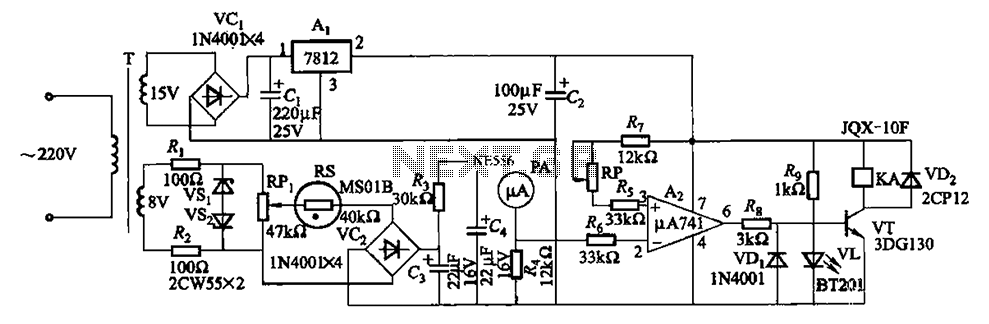
The humidity alarm system is based on integrated circuits and relays, utilizing the pA741 circuit. The MS01 employs a wet-type humidity resistance element as a probe. When the humidity exceeds a predetermined value, specifically set at 6 feet high,...
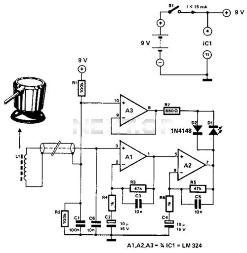
The circuit utilizes the principle that in an RL circuit, the pulse width across the inductor is proportional to the inductance. This circuit indirectly measures the inductance using a digital voltmeter (DVM). The measurement range is approximately 5 to...
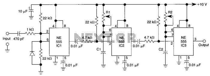
Three 555 IC timers are utilized in this circuit to create a simple delayed-pulse generator. IC1 functions as a waveform shaper to generate a rectangular waveform. IC2 generates a delaying pulse that triggers IC3 on the trailing edge of...
The main purpose of this design is to address a minor flaw in the widely used Fridge Door Alarm circuit, which has been available on this website since 1999 and has been constructed by many hobbyists. This circuit ceases...
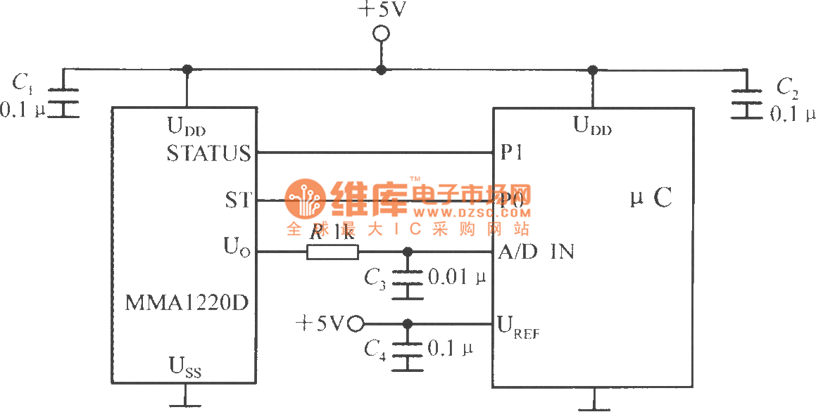
The microcontroller within the A/D converter can utilize a PIC MCU produced by Microchip. The MMA1220D's state and self-test pins are connected to the P1 and P0 ports of the microcontroller, with its output voltage sent to the input...