
tesla

The low-voltage demonstration Tesla coil presents a significant advancement in Tesla coil technology by integrating modern solid-state components that enhance performance and safety. The use of a photovoltaic relay to replace the traditional spark gap not only simplifies the construction process but also improves reliability and efficiency. The isolated LED provides a clear visual indication of operation, while the silicon photovoltaic stack ensures effective energy conversion to drive the bidirectional FET. The careful selection of inductance and capacitance values based on theoretical calculations allows for optimized performance, ensuring that the energy transfer between the primary and secondary circuits is maximized.
In practical applications, the low-voltage Tesla coil can serve as an educational tool, demonstrating principles of electromagnetism and resonance without the inherent dangers of high-voltage systems. The continuous oscillations in the secondary circuit after the primary circuit interruption showcase the energy retention capabilities of the system, allowing for prolonged demonstrations. Furthermore, the compact and lightweight design facilitates portability, making it suitable for experimental setups in various educational environments.
Future developments may focus on refining the design for improved efficiency and exploring additional applications, such as wireless power transmission experiments or advanced demonstrations in physics education. The integration of modern diagnostic tools could also enhance the understanding of the underlying principles, allowing for more precise measurements and comparisons to theoretical models. Overall, this innovative approach to Tesla coil design represents a blend of historical ingenuity and contemporary engineering, fostering continued interest in the fascinating world of high-frequency electromagnetic phenomena.A low-voltage demonstration Tesla coil using a solid-state photovoltaic relay to replace the conventional spark gap has been analyzed and then built. This relay incorporates an isolated LED to illuminate a silicon photovoltaic stack which drives a bidirectional FET.
Component values for the inductances and capacitances have been determined theoret ically from measured parameters. Computer simulation by integrating the coupled circuit equations shows excellent agreement with oscilloscope traces. Energy transfer between the primary and secondary circuits is demonstrated, along with continuous secondary oscillations after the primary circuit is interrupted.
This low-voltage design is easier to build and diagnose than high-voltage Tesla coils. Nikola Tesla invented the Tesla coil late in the nineteenth century, exploring many high-power variations in his Colorado Springs laboratory (1). They were all basically air-cored high-frequency transformers, generating very high voltages. Many of his experiments were complicated, using large coils made with heavy copper wires to conduct very high currents.
His high-voltage capacitors used hundreds of salt water-filled Leyden jars made from the local Manitou Springs mineral water bottling plant. Tesla documented his achievements with multiple-exposure photographs which show his small wooden building filled with curved sparks up to 40 m in length.
Using spark length is how Tesla often diagnosed his experiments. Tesla`s ultimate goal was to generate high enough voltages that he could transmit useful electrical power freely through the atmosphere. One contemporary account claimed he succeeded in sending enough power to energize a bank of light bulbs 40 km away (2).
However, he never completed his final and largest experiment on Long Island, New York, which he designed inside a 60-m-high wooden tower. Although lack of funding was the primary reason the tower was torn down, in the light of today`s knowledge, it never would have succeeded in the manner he envisioned.
While Tesla was advanced for his time, he didn`t have electronic diagnostic tools to study his experiments. Even though Tesla`s grandiose plans would not have worked, we remain fascinated with high-voltage Tesla coils.
Generating fiery arcs and lighting fluorescent tubes at a distance are always exciting demonstrations. In the last 60 years, instructions for building high-voltage Tesla coils appeared occasionally in popular magazines, journals, newsletters, and books (3-13).
A useful instrument in many physics laboratories is the hand-held Tesla coil used to excite gas discharges and find leaks in vacuum systems. There has also been some interest in using very large Tesla coils to test military aircraft with simulated lightning, (14) and using smaller coils to generate electron beams (15).
While any of these Tesla coils can be experimental subjects, detailed measurements to compare with theoretical predictions requires sophisticated equipment to deal with high voltages. A conventional Tesla coil consists of tuned primary and secondary circuits. An interrupter in the primary circuit stimulates oscillations from the charge stored in a large capacitor.
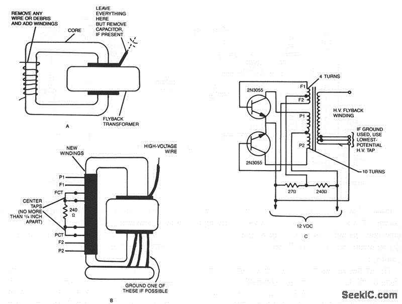
The primary circuit interrupter design is critical to maximize power transfer to the secondary circuit. High-power Tesla coils use variations on rotating spark gaps to extinguish the high-voltage spark, (16), a technique that hasn`t changed since Tesla used it!
This paper replaces that "ancient" element with modern integrated circuit technology. A BOSFET (Bidirectional Output Switch Field Effect Transistor), while not capable of high powers, has the necessary properties which make a demonstration Tesla coil practical. MOSFETs make up the BOSFET, which are combined with an optically coupled LED driver in a small integrated circuit package, manufactured as a photovoltaic relay.
(17) It turns on and off quickly, exhibits a low ON- 🔗 External reference
Related Circuits
A small Tesla Coil (12-inch range), Jacob's Ladder, or an "Antigravity Project" from the book "Electronic Gadgets for the Evil Genius" is being discussed, but sourcing parts for these projects has proven challenging. The book is informative, yet the...

Four 4.8 Volt 2000mA Nickel Cadmium batteries require a safe method for initial charging using a lab power supply, as a specific NiCad charger is not available. Assistance is sought for circuit drawings of a simple NiCad charger. The...
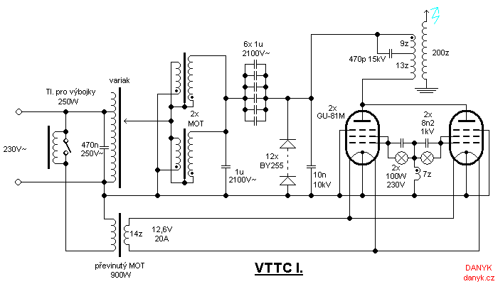
The Vacuum Tube Tesla Coil (VTTC) is a Tesla coil that utilizes vacuum tubes as switches. It features a self-oscillating circuit with two Russian GU-81M tubes connected in parallel. High voltage is sourced from two Microwave Oven Transformers (MOTs)...
This coil operates from 12V or 24V SLA batteries. A pair of car ignition coils is used to provide approximately 20kV for charging the capacitor bank. The ignition coils are driven by a variable frequency square wave generated by...
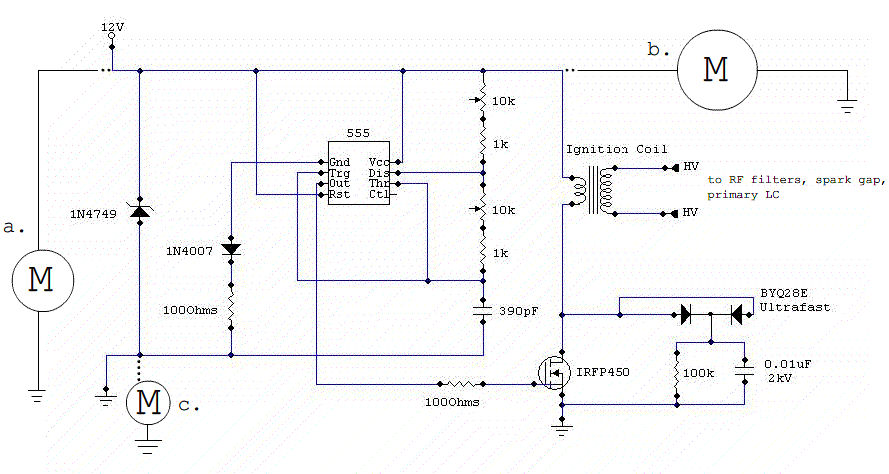
A small DC Tesla coil is being constructed with a rotating spark gap. The motor controlling the rotary spark gap draws approximately 3.8 amps of current at full load, while the 555 control circuit consumes about 4 amps. The...
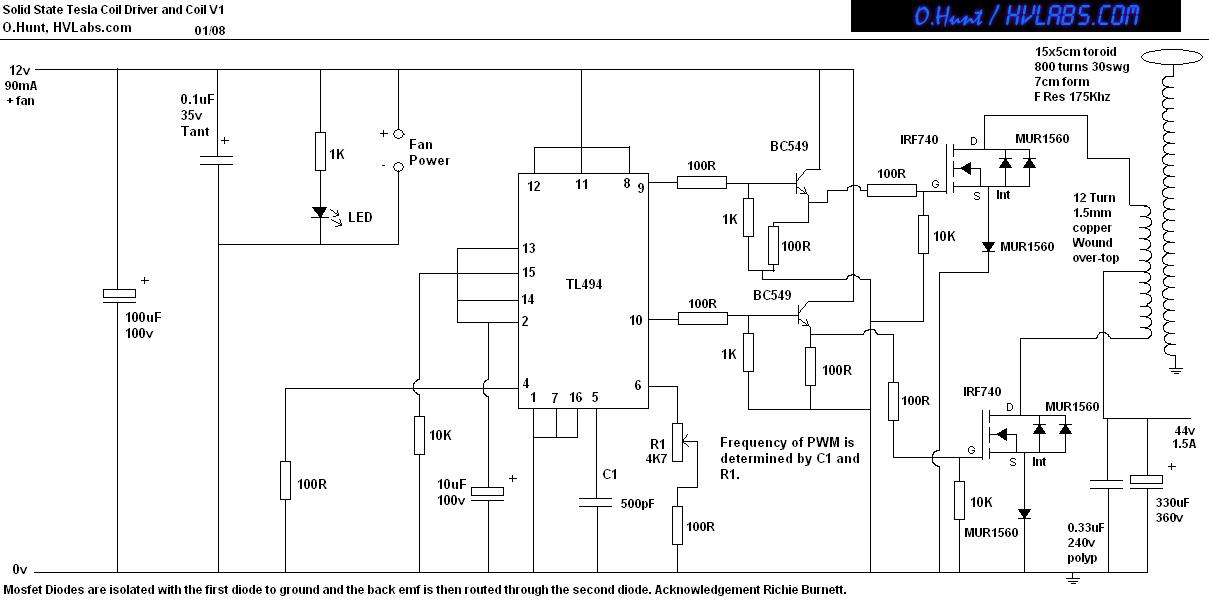
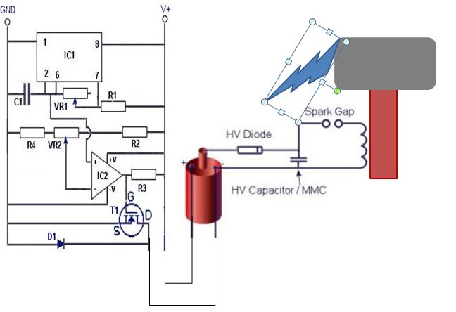
This is a solid-state version of a Tesla coil, replacing the spark gap with MOSFET transistors and utilizing a close-coupled primary coil without capacitors. The method of driving the primary coil varies among designs. After researching various works online,...