
Tesla Switch
Warning: Undefined array key "extension" in /var/www/html/nextgr/view-circuit.php on line 477
Deprecated: strtolower(): Passing null to parameter #1 ($string) of type string is deprecated in /var/www/html/nextgr/view-circuit.php on line 477

To create a simple NiCad charger for four 4.8 Volt 2000mA Nickel Cadmium batteries using a lab power supply, a basic understanding of the charging process and circuit design is essential. The charger should be designed to provide a constant current charge, typically at a rate of 0.1C to 0.3C for NiCad batteries, which translates to a charging current of 200mA to 600mA for these batteries.
A recommended circuit configuration involves using an LM317 voltage regulator to maintain the desired output voltage. The input voltage to the LM317 should be set to at least 1.5V higher than the total voltage of the battery pack to ensure proper regulation. For four 4.8V batteries in series, the total voltage is 19.2V, necessitating a minimum input voltage of approximately 20.7V. Additionally, a heat sink must be employed on the LM317 to dissipate heat generated during operation, especially when charging at higher currents.
The circuit can be enhanced with a current limiting resistor or a constant current source configuration to prevent overcharging. A simple transistor-based switching mechanism can be included to control the charging process, allowing for automatic shut-off when the batteries reach full charge. This can be achieved by monitoring the voltage across the battery pack and disconnecting the charger when a certain threshold is reached, typically around 5V per cell.
For relay control, solid-state relays (SSRs) are recommended for their fast switching capabilities and reliability. The SSRs can be triggered by a 555 timer configured in astable mode to generate a pulse train, allowing for precise control over the charge cycles. The design should include appropriate fuses to protect against short circuits and ensure safe operation.
In summary, the charger circuit should consist of an LM317 voltage regulator, a heat sink, current limiting components, and solid-state relays controlled by a 555 timer. This setup will ensure safe and efficient charging of the Nickel Cadmium batteries while extending their operational lifespan and performance in applications such as powering an electric bicycle.Four 4, 8 Volt 2000mA Nickel Cadmium batteries. Does anybody here know a safe way of initial charging those batteries from a lab power supply I do not have a NiCad charger so I need to make one. Any circuit drawings of a simple NiCad charger I will be glad to get some help on this. I have four 4, 8 Volt 2000mA Nickel Cadmium batteries. Does anybody here know a safe way of initial charging those batteries from a lab power supply I do not have a NiCad charger so I need to make one. Any circuit drawings of a simple NiCad charger I will be glad to get some help on this. You have a minimum of 4*4. 8 V input voltage need + the required voltage drop of either the LM317 or the transistors, so you need to choose your power supply output accordingly. I think you need some heat sink on the active pass device too. Well that sure is a lot of trannies but if it works, great deal. I have finally decided to put together a relay powered one to play with. Had to pack the relays in foam to quiet them down. Was very surprised to find what I did. Using 4 4. 5 ah 12v and driving a 1amp motor, I already have 4. 5 hours run time logged and have dropped from 13v down to 12. 8. I have a switch time of around 12 a second. I am depleting the batteries but at a very slow rate. At 1 amp, I should have killed the bats by now. So to conclude, I see this upping the run effective run time for the motor. As I intend to run an electric motor to power my bike, this should give me a greater distance of travel overall.
Will look into solid state relays for the switching as they will trigger on 5 v and can use a 555 to run the pulse train with. The other board still has a heat problem with transistor 6 and I cannot figure out why. I have been over the circuit many times and its wired exactly as the diagram states. The only problem is if I lose a relay, I will have a dead short on one side every half cycle. Had to fuse between each pair and both sides as well. So far so good. More run time to see what will give. Next is to recharge and see how many consecutive hours run time the system will give without going below the 12.
4 save level as these are the standard gel cells. Well guess its time to lay it down for all to see. I have finished my 4 batt switch and it runs using relays at 20 cps. I will be subbing them with SS relays so I can up the transfer time. I am able to have a 3 amp motor run under load for extreme long times. This motor will be used for an electric bicycle. From estimates I am seeing around 100 miles and that is with 4. 5 ah batts. I actually will be using 18 ah on the bike. Nothing will tell better than the trip out the highway soon. The motor will be driven by pwm from the 4 batt switch. I did notice that I had no output from the tesla switch with the two caps in place. As soon as I removed them, I then had over 12v and high amps available from the FWB output. The motor I use right now is an old windshield wiper motor from a 80`s vintage GM. I got the largest motor available and it has a worm gear to another gear reduction. I use a 8500uf 85v cap to pad the output during switch times. Well after all my attempts to make a drawing for all of you all I could was a bmp and cant upload them. Circuit maker saves in native format only "ckt" and not sure any of you can see it. This is frustrating as heck. A simple thing and yet no cigar. The circuit in d3 had diodes I do not use. I simply use a SS relay for each batt connection and then trigger series on one side while parallel on the other.
The inline caps have to go as they impede the flow. The SS relays will make the switching a seperate circuit from the motor. It could be run on the same one for the lights as well. No inductive kickback to kill the timer. S1 is the master on off. S2, 6, 7 on and S3, 4, 5 off and alternate back and forth. Since the SS relay is internal led driven just need to use the direct output of the 555 timer a 🔗 External reference
Related Circuits
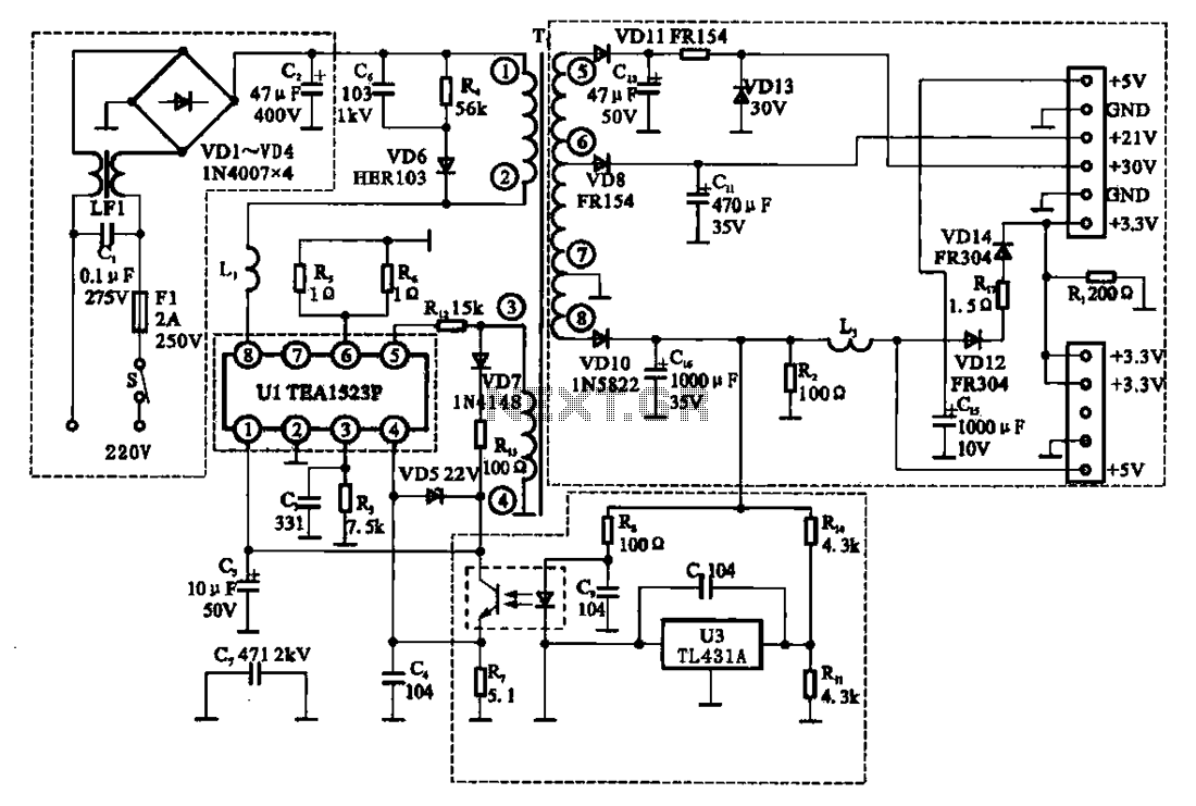
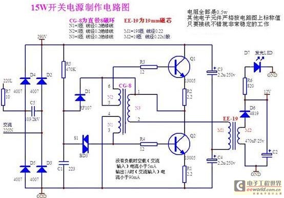
The East Shi IDS-2000F STB switching power supply circuit primarily consists of an AC input circuit, a switching oscillation circuit, an output circuit, and a secondary steady voltage control circuit. The AC input circuit includes a switch (S), fuse...
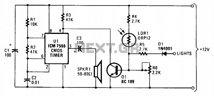
As dusk begins to fall, the sensor, which is a cadmium-sulfide light-dependent resistor (LDR), activates a small horn to provide an audible reminder to turn on the lights. The circuit can be turned off by simply switching on the...
This is a 220V touch switch circuit. This circuit functions as a switch that turns off and on the electronic device connected to the 220V home supply. The 220V touch switch circuit is designed to control the operation of electrical...
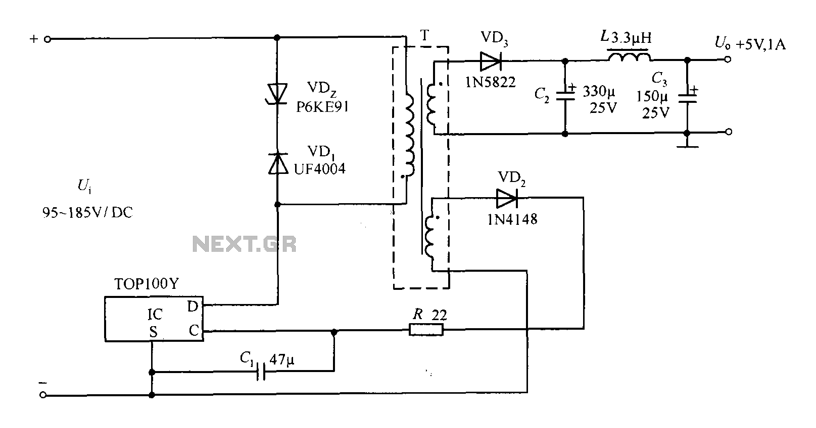
The TOP100Y is a flyback DC switching power supply circuit with a +5V, 1A output. This power supply features a feedback circuit that directly regulates the output voltage, making it suitable for applications that require electrical isolation and minimal...
A daily switching power supply primarily provides direct current (DC) power to electronic devices. The required DC voltage for electronic devices typically ranges from several volts to over ten volts, while the input voltage from the mains supply is...
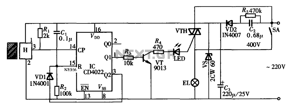
The circuit illustrated in the figure depicts an automatic bathroom light switch system. When the door is opened, the light is activated, illuminating the space. Conversely, when the door is opened again, the light turns off. The circuit comprises...