
TESLA COIL BUILT

Additional information includes the acquisition of knowledge about TV circuits and flybacks, with plans for multiple projects, including building a homemade oscilloscope. A previous attempt to create an "ocilograph" from a black-and-white TV in the mid-1990s resulted in a weak image due to imperfect drivers and amplifiers for the deflection coil. The experience gained from this project has informed the current plans. Various methods have been employed to drive flyback or Line Output Transformer (LOPT) transformers, including Hartley oscillators and a custom Zero Voltage Switching (ZVS) circuit. The preferred method now involves a flexible synthetic oscillator and MOSFET combination, utilizing a 555 timer and power MOSFET IRFP260 to maximize flyback performance without damage. This led to the development of the Coil Driver 1628, which powers a TV flyback and subsequently the Tesla coil circuits.
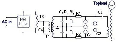
Although utilizing a TV flyback to operate a 150 kV Tesla coil is not unprecedented, there is little documentation available online about this approach. The decision to use a large TV flyback was driven by budget constraints and the need to repurpose available materials. The primary coil is constructed from old TV coaxial cable, while the coil itself is wound around an old plastic bottle. An adjustable arc chamber was created inside a pill container, which produces surprisingly loud sounds due to the slow arcs that generate insufficient heat to melt the plastic, allowing for easy arc adjustment.
The largest Tesla coils powered by flybacks operate at a pulsed frequency, unlike the constant 60 Hz output from a Neon Sign Transformer (NST), resulting in reduced heat generation and facilitating quieter arc chamber designs. After saving funds, a 12 kV NST was purchased and modified to eliminate the Ground Fault Interrupter (GFI) circuits, enabling the construction of a new primary coil, again made from useful old TV coax. The GFI circuits were removed due to their tendency to shut down the NST when used with a Tesla coil, which generates significant voltage and RF fluxes. Caution is advised when tampering with GFI circuits, as improper handling can be extremely dangerous. It is recommended to obtain a New Old Stock (NOS) transformer or one from a jurisdiction without stringent GFI regulations, as these devices do not effectively prevent electric shocks or fire hazards. Testing revealed that the GFI circuits could allow an arc to persist for over 10 minutes under load, posing substantial risks.
The commentary regarding GFI regulations is noted, but the primary focus remains on the technical aspects of the Tesla coil construction and operation. The images provided do not depict the coil powered by an NST, as they feature alternative power sources.A full foot long arc and get to more then 1million volts eventually. I have finally built a REAL Tesla coil that operates via an arc and capacitor combination. Not just a flyback or transformer setup in series. It was not as difficult as I thought it might be, and since my successful Coil Driver circuit was perfected I have been able to run a lot of things. I also learned a great deal about TV circuits and Flybacks. I have many projects planned, one is to build my own O-scope from scratch. I have done something similar before-back in the mid 1990s I built a "ocilograph" from scratch with a B&W TV but the picture was weak and I never perfected the drivers and amplifiers for it`s deflection coil. I now know how to do so. This is one of my planned projects. I have used many means to drive flyback or LOPT transformers from old TVs to homemade AC ones. Hartley Oscillators to my take on the ZVS as I posted before-and now, my favorite, a flexible synthetic oscillator and mosfet combination.
Simply a 555 and power mosfet IRFP260 was my obvious choice for getting the most out of flybacks without burning them out. Thus the Coil Driver 1628 was born, which I will explain later-powers a TV flyback and here thus the Tesla coil circuits.
I am sure I am not the first one to ever use a TV flyback to run a 150Kv Tesla coil-however-I have never seen anyone do it on the Internet or anywhere else. I decided to power my coil with a large TV flyback (yes DC due to it`s built in diodes)- as I had no choice.
I simply had to- on a very low budget put this coil and two others together with whatever I had laying around. The primary is made of old TV coax, the coil itself wound around an old plastic bottle. I built the adjustable arc chamber inside a pill container which surprised the very loud sounds it made (possible since the arcs are slow and thus not enough heat generated to melt the plastic-makes for easy adjustment of arc).
Since my largest Tesla coils powered by flybacks run at a pulsed frequency rather then the more constant 60hz a NST (Neon Sign Transformer) will produce the heat generated is less and arc chambers that keep things quiet are more easy to make. I have since saved my pennies and ordered a 12Kv NST which I got and modified so that I did not have to worry about any GFI circuits and got a coil going over night with a new primary-again made of very useful old TV coax!
I had to remove the darn GFI "smart" circuits because they will shut down an NST if it is used to power things like a Tesla coil since they produce many voltage and RF fluxes. I made short work of the GFI circuits only because I have a very good understanding of transformers and high voltage transformers.
Do not attempt to remove a GFI from an NST unless you really know what you are doing it can be VERY DANGEROUS. It is better to buy a NOS (New Old Stock) transformer or transformer from another country that does not have the crazy GFI laws.
Funny thing is, they don`t prevent you from being shocked or fires from starting very well! I was surprised at this, it took several min before the GFI circuits did anything about serious fault problems and I was not even in "setup mode". My tests showed that with the GFI an arc could run for more then 10min with a load, plenty of time to start a fire or shock someone.
The GFI circuits and the law to need them is a joke when it comes to the NST! I really despise big brother laws like that-and putting chips in everything to protect mainly adults from ourselves. This site is not about politics-however. None of these pictures show the coil powered with an NST-they are all with the coil powered 🔗 External reference
Related Circuits
The Pulsed Multiple Gas (PMG) laser discussed in this chapter closely resembles the Home-Built Pulsed Argon and/or Krypton (Ar/Kr) Ion Laser from Scientific American. However, the PMG laser's developers have also utilized xenon (Xe) and oxygen (O2) and even...
Instructions for constructing a 1kW synchronous rotary spark gap (SRSG) Tesla Coil. This device operates using mains power and is powered by a 1kVA (10mA, 10kV) neon sign transformer (NST). The construction of a 1kW synchronous rotary spark gap Tesla...
This circuit generates sine, square, and triangle waves ranging from 0.1 Hz to 1 MHz. It includes a counter that measures the frequency of the function generator or an external signal with a peak-to-peak voltage of a few volts,...
An inexpensive control system has been developed, costing less than $70, to enhance the cutting power and accuracy of home-built DC discharge laser systems. This control system employs a technique known as Pulse-Per-Inch (PPI) control, which pulses the laser...
Tesla's free-energy receiver was patented in 1901 as An Apparatus for the Utilization of Radiant Energy. The patent refers to "the Sun, as well as other sources of radiant energy, like cosmic rays." That the device works at night...
Single transistor flyback driver caused many problems due to its operating principle. I received e-mails from people who were unable to get it functional even when they are sure that their flyback and transistor are OK. In addition, since...