
220V Touch Switch

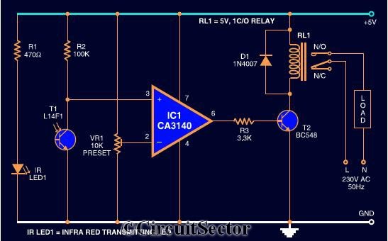
The 220V touch switch circuit is designed to control the operation of electrical devices by utilizing a touch-sensitive mechanism. This circuit typically consists of a touch sensor, a relay, and the necessary supporting components to ensure safe operation with high voltage.
The touch sensor acts as the primary input device, detecting the user's touch and sending a signal to the control circuitry. When the sensor is activated, it triggers a relay, which serves as an electromechanical switch. The relay is rated to handle the 220V AC voltage and can control the power supply to the connected device.
Key components of the circuit include a resistor, which may be used to limit the current flowing through the touch sensor, and a capacitor that can help filter noise from the signal. Additionally, a diode is often included in parallel with the relay coil to protect the circuit from back EMF generated when the relay is switched off.
To ensure safety and reliability, the circuit should be enclosed in a suitable housing to prevent accidental contact with live components. Proper insulation and adherence to electrical standards are critical when designing circuits that operate at 220V to prevent hazards such as electric shock or fire.
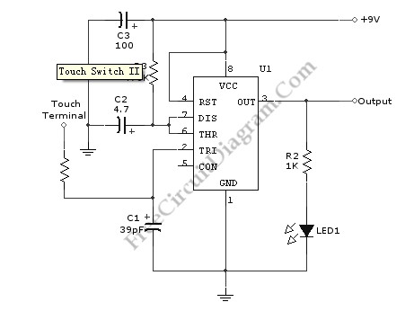
Overall, this touch switch circuit provides a convenient and modern solution for controlling household appliances, enhancing user experience through simple touch activation.This is a 220V Touch Switch circuit. This circuit is used as switch which turn off and turn on the the electronic device that is connected to the 220V home.. 🔗 External reference
Related Circuits
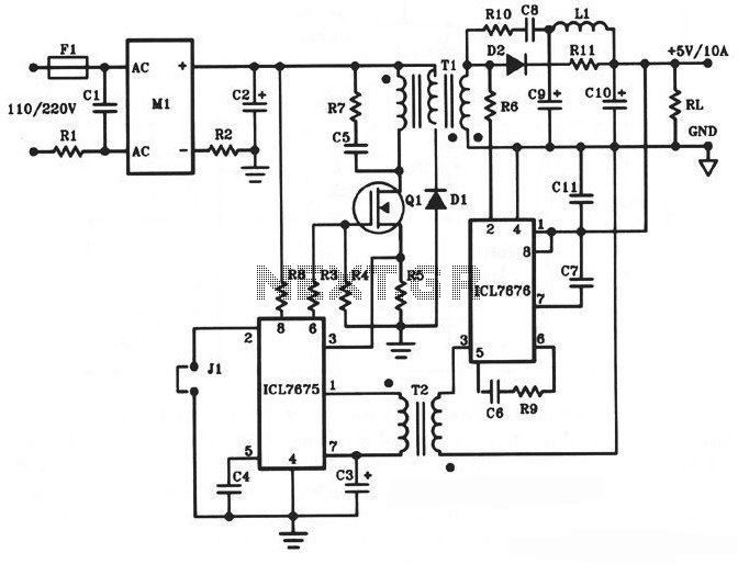
The following diagram illustrates a 50W offline switching power supply circuit design. This circuit is powered by a MOSFET, specifically the BUZ80A/IXTP4N8 for a 220V AC voltage input and the GE IRF823 for a 110V AC voltage input. The...
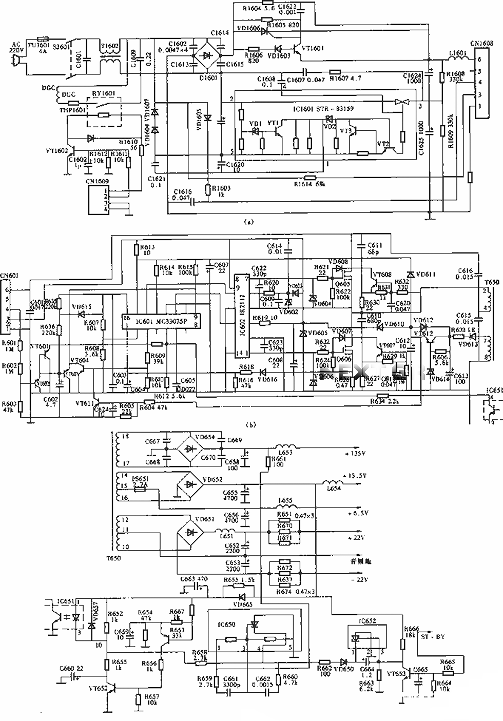
The circuit of the Sony KV-S29MHl (S Movement series) TV switching power supply (SIR a 80145A) consists of three main sections: (A) the power oscillation part, (B) the regulator part, and (C) the output section. The Sony KV-S29MHl TV switching...
The circuit diagram presented is a highly sensitive wireless relay switch designed to control home appliances such as flush systems and hand dryers. This wireless switch operates without the need for a remote control. It functions by simply moving...
This circuit switches a printer's USB connection between a PC and a laptop. The goal was to create a method for allowing the laptop to use the printer occasionally while maintaining the printer's connection to the PC at all...
Utilizing the specified values depicted in the schematic diagram, this circuit features a timed ON period of 4 seconds. The ON time is governed by the values of capacitor C2 and resistor R3; increasing either C2 or R3 will...
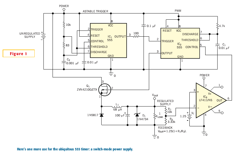
Most switch-mode power supplies utilize a PWM (pulse-width-modulated) output that is regulated through voltage feedback. A 555-timer IC can be used to generate PWM at a low cost. The circuit diagram illustrates how to convert a 555 PWM circuit...