
Test Signal Generator

The signal generator described employs a three-channel Digital-to-Analog Converter (DAC) to produce both Composite Video Signal (CVBS) and S-Video (Y/C separated) outputs simultaneously. The architecture utilizes one channel of the DAC to generate the Y (luminance) component while the other two channels are utilized for the color components in the Y/CB/CR format. The design acknowledges the impending obsolescence of the NTSC television system, which may necessitate a shift to more modern video formats.
In the schematic, the DAC's three output channels are configured to interface with respective video processing circuits. The first channel outputs the Y component, which is essential for both CVBS and S-Video formats. The second channel is dedicated to the Cb (blue-difference chroma) component, while the third channel handles the Cr (red-difference chroma) component, enabling the generation of high-quality component video signals.
The design includes necessary filtering and buffering stages to ensure signal integrity and minimize distortion across the outputs. The CVBS output is derived from combining the Y, Cb, and Cr signals, while the S-Video output is achieved by separating the Y and C signals, allowing for improved video quality through reduced cross-talk between luminance and chrominance.
This dual-output capability enhances versatility, making the signal generator suitable for various applications, including testing and interfacing with both legacy NTSC systems and newer component video standards. The design reflects an awareness of the evolving landscape of video technology, ensuring compatibility with both current and future standards.This signal generator uses a three channel DAC to generate Composite video signal (CVBS) and S video signal (Y/C separated) at the same time, left one channel is not used in NTSC format. It is assigned for one of the color components of Y/CB/CR video format. This feature was not planned some years ago, but it has been added when started to draw the schematic this year, because NTSC television system might be obsoleted in the near future. The two different video format, component video and NTSC video, work in 🔗 External reference
Related Circuits
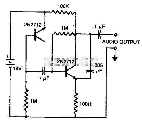
A reverse-biased pn junction of a 2N2712 transistor is utilized as a noise generator. The second 2N2712 functions as an audio amplifier. A 0.005 µF capacitor placed across the amplifier output eliminates certain high-frequency components, allowing for a closer...
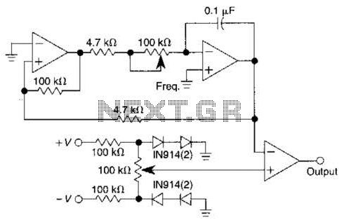
This pulse generator utilizes a single integrated circuit (IC) and six passive components to achieve a frequency range of 400 to 4000 Hz, with an adjustable duty cycle ranging from 1% to 99%. The circuit employs a threshold detector...

The term VCXO refers to a Voltage Controlled Crystal Oscillator. The frequency of this oscillator can be fine-tuned by varying the control voltage. VCXO clock generators are utilized in a range of applications, including digital telecommunications. VCXO circuits are essential...
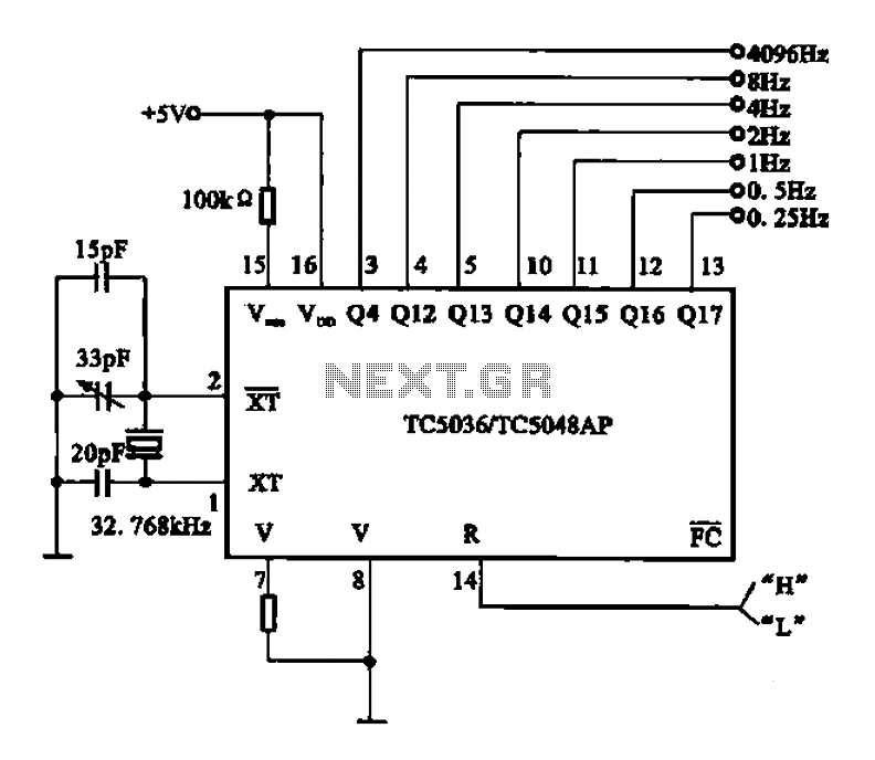
32.768 kHz; In MP3/MP4 devices, mobile phones, laptops, and other digital products, a real-time clock signal generating circuit is utilized, primarily composed of crystal resonators and TC5036/TC5048AP chip oscillators. This setup produces a raw 32.768 kHz crystal oscillator signal,...
This sine wave generator is adjustable between 15 Hz and 150 kHz. The circuit is essentially a Wien-bridge oscillator, featuring multiple capacitor selections. The sine wave generator operates on the principle of the Wien-bridge oscillator, which is known for producing...
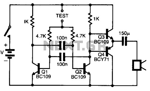
The pitch of the tone is dependent upon the resistance under test. The tester will respond to resistance of hundreds of kilohms, yet it is possible to distinguish differences of just a few tens of ohms in low-resistance circuits....