
Variable Frequency Sinewave Generator

The sine wave generator operates on the principle of the Wien-bridge oscillator, which is known for producing low-distortion sine waves. The frequency range of 15 Hz to 150 kHz allows for versatile applications, including audio signal generation and testing of audio equipment.
The circuit design incorporates resistors and capacitors that form a bridge configuration, allowing for frequency adjustments by selecting different capacitors. The Wien-bridge oscillator typically includes a variable resistor that aids in stabilizing the amplitude of the output signal, ensuring consistent waveform characteristics.
In this particular design, the oscillator can be fine-tuned to achieve the desired frequency by adjusting the capacitor selection. The multiple capacitor options provide flexibility, enabling the user to select the appropriate value for the application at hand. The output can be taken from the oscillator's output node, which provides a clean sine wave signal suitable for various uses.
Power supply considerations should also be addressed, as the circuit typically requires a dual power supply to maintain proper operation across the frequency range. Additionally, incorporating a buffer amplifier at the output can improve the drive capability of the sine wave signal, allowing it to interface effectively with other circuit components or systems.
Overall, this sine wave generator circuit is an essential tool in electronic testing and signal processing, offering adjustable frequency output with low distortion characteristics, thanks to its Wien-bridge oscillator configuration.This sine wave generator is adjustable between 15 Hz to 150 kHz. The circuit is basically a Wien-bridge oscillator, with multiple capacitor selection. Here is. 🔗 External reference
Related Circuits
A function generator that operates within a frequency range of 0.1 Hz to 20 MHz can be constructed using the MAX038 integrated circuit chip. This represents a straightforward implementation of a high-performance signal generator. The MAX038 is a high-speed precision...
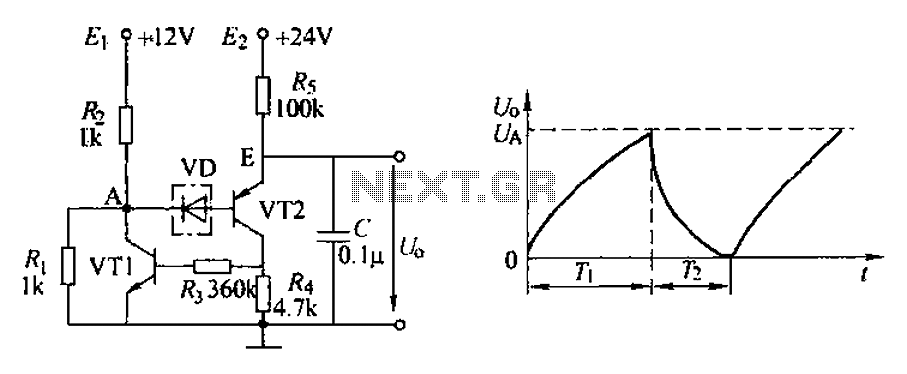
The application circuit depicted is a complementary sawtooth generator. In the schematic, VT1 is the transistor with a base current limiting resistor, which prevents excessive base current flow through the crystal tube. The resistor R4 acts as a bleeder...
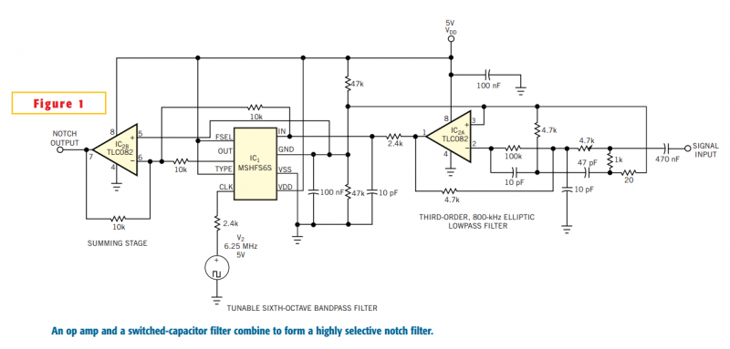
Although you can obtain universal, resistor-programmable switched-capacitor filters that are configurable as notch filters, most cannot operate at bandwidths higher than 100 kHz. Further, the typically 16- to 20-pin packages do not include a continuous-time, antialiasing filter to prevent...
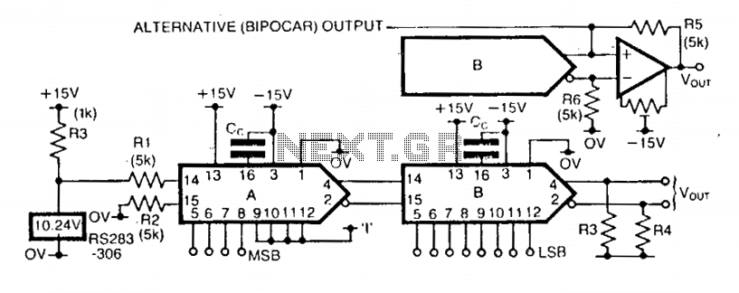
The step size of the converter is variable by selecting the high-order data bits. The first DAC, A, has a stable reference current supplied via a 10.24 V reference IC and resistor R1. Resistor R2 provides bias cancellation. Only...
This is a highly effective RF attenuator circuit that operates within the frequency range of 300 kHz to 3 GHz, utilizing the quad PIN diode array HSMP-3816 from Avago. The lower PIN diodes are biased at 1 mA, resulting...
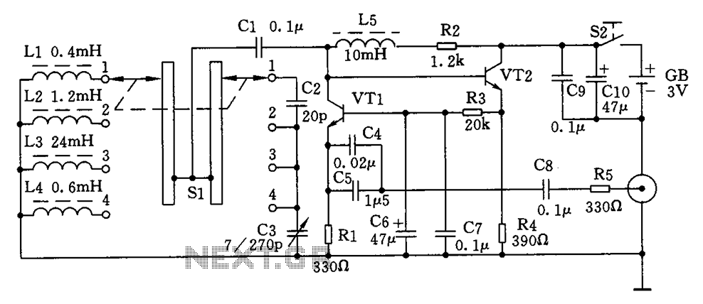
This is a simple high-frequency signal generator. By changing the inductance of the LC resonant circuit using the band switch S1, the high-frequency oscillation frequency range can be altered. The generator is divided into four frequency stages: the first...