
testing ddl s circuit

To properly test a DDL (Direct Drive Laser) circuit before adding the LD (Laser Diode), several steps must be followed to ensure the circuit functions correctly and safely.
1. **Preparation**: Gather necessary tools including a multimeter, oscilloscope, power supply, and appropriate test loads. Ensure that all components are rated for the specifications of the DDL circuit.
2. **Visual Inspection**: Begin with a thorough visual inspection of the circuit board and components. Look for any signs of damage, such as burnt traces, cracked components, or incorrect solder joints. Ensure that all components are properly placed according to the schematic.
3. **Power Supply Check**: Before applying power, verify that the power supply voltage matches the specifications of the DDL circuit. It is critical to ensure that the polarity is correct to prevent damage.
4. **Initial Testing**: Power the circuit without the LD connected. Measure the voltage at various points in the circuit with a multimeter to ensure that the expected voltages are present. This includes checking the supply voltage and any reference voltages required by the circuit.
5. **Signal Testing**: Use an oscilloscope to analyze the output signal of the circuit. Check for the correct waveform shape and frequency. This step is crucial to confirm that the circuit is generating the appropriate signals to drive the LD once it is connected.
6. **Load Testing**: If the circuit includes a test load, connect it and observe the circuit's behavior under load conditions. Monitor for any fluctuations in voltage or current that may indicate issues within the circuit.
7. **Final Verification**: After all tests have been completed and the circuit has been confirmed to be functioning correctly, it is safe to proceed with integrating the LD. Ensure that the LD is correctly oriented and connected according to the schematic.
By following these steps, the DDL circuit can be effectively tested to ensure reliability and performance prior to the addition of the laser diode. This process helps prevent potential damage to the LD and ensures optimal operation of the entire system.I am about to post a How To on testing DDL`s circuit before adding the LD, I hope it is all pretty clear and with no errors. Those .. 🔗 External reference
Related Circuits

The circuit illustrated in Figure 4 is an AC timing circuit designed to operate for 4 hours. It utilizes the BH4024, a 7-stage serial binary counter/divider, in conjunction with a 555 timer circuit. The circuit is activated by a...
The PIC16C57-RCT is a communication single-chip microcomputer integrated circuit that is commonly utilized in the Qiao Xing series of IC card management telephones. The PIC16C57-RC integrated circuit features a pulse and dual-tone dialing circuit, memory data and clock circuit,...
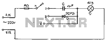
The figure illustrates a basic dimming lights circuit. The light intensity is controlled by a multi-speed control switch, designated as K. When switch K is set to position "1," the lights are turned off. In position "2," the light...
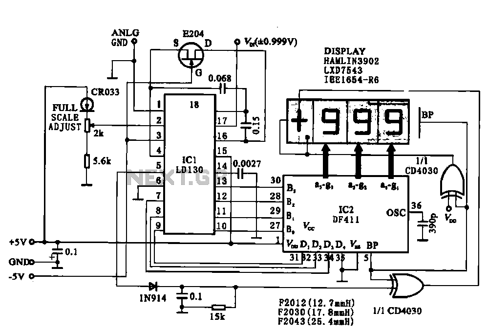
This circuit illustrates a display driving system for a digital voltmeter. The liquid crystal display (LCD) does not emit light by itself; it relies on external incident light for visibility. The integrated circuit (IC) LD130 serves as an input...
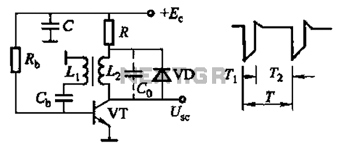
Common non-sinusoidal oscillator circuit, waveform and frequency formula - sawtooth oscillator - use blocking oscillator The sawtooth oscillator is a type of non-sinusoidal oscillator that generates a waveform characterized by a linear rise in voltage followed by a rapid drop....

The R-C twin-tee passive circuit provides band-reject (notch) filtering suitable for portable applications. It has a loaded circuit Q of 0.25. Effective rejection is achievable when the bridge is balanced, which requires close tolerances of the adjustable components, and...