
A practical MS Decoder Circuit

To facilitate phase adjustments, patch cords can be utilized if the console supports phase switches, though caution is advised as some consoles only provide phase switching on the channel microphone preamp rather than the channel itself. By patching out of the preamp on the first channel and into the line input of the next channel, it may be necessary to employ a half patch technique, which is not covered in this discussion. Prior to panning hard left and right, both channels should be centered, and the level on the second channel should be adjusted until the Side signal is completely canceled, indicating matched signal levels. Once this is achieved, one channel can be panned hard right while the other is panned hard left. Most multi-track audio programs, such as Studio Vision Pro and Pro Tools, offer similar functionalities. The Side signal can be sent pre-fader to an effects bus, with the original channel panned hard right. The effects bus can then phase invert the signal and pan it to the opposite channel of the original, completing the setup.
The primary advantage of utilizing a dedicated MS Decoder lies in the ability to monitor the effect in real-time while positioning microphones and making adjustments prior to recording. Past experiences have shown that recording Mid and Side signals directly may not yield compatible results during playback and mixdown, underscoring the importance of this real-time monitoring capability.The schematic diagram of the MS Decoder may look complicated but is actually quite simple. Both the Mid and Side signals are initially buffered by unity gain inverting buffers formed around IC1b and IC2 b. This is necessary for two reasons, first to ensure enough drive current for the following sections. Second, the final summing sections invert t he signal, to achieve zero phase shift through the unit, one more stage of phase inversion is required. The Mid signal goes to level control potentiometer R15. It is then fed equally to the left and right summing amplifiers, which are formed around the two sections of IC3.
The use of R15 (and R16) is to allow adjustment of the relative levels of the mid/side levels independent of the mic-pre gain setting. This is useful for directly feeding a recording device. The Side signal has a little different path. After initial buffering, it is fed to the right summing amplifier via one section of dual potentiometer R16.
It is also fed to a unity gain inverter formed by IC2a and its associated resistors. This inverted signal goes to the other half of the dual ganged potentiometer section. Then it is summed into the left channel via IC3a. One section of IC1 is not used. Both of its inputs are tied to ground to keep any thing strange from happening. OK, so what are R19 and R20 doing That is an interesting question. These are there to load down R16 so that when the levels of the Side signal are adjusted the potentiometer gives the same feel as the Mid level adjustment potentiometer R15. The op-amp summing sections are virtual grounds. This means that signals entering the op-amp see a load equal to the input resistor. All of these are 10K resistors. The Mid potentiometer feeds two of these so it is presented with a 5K load. To make the load on the Side potentiometer the same one additional 10K resistor tied to ground is added to each wiper so it sees 5K also.
Here is the other interesting thing that all of this causes. Because all the potentiometers are linear taper, loading them down with a load much smaller than the resistance of the potentiometer causes a change in the characteristics of the potentiometer. This in essence, makes them respond more logarithmically than linearly, which is the way we hear anyway which is a good thing!
Well, you can always break out the patch cords if your console supports phase switches. Be careful, some only have the phase switch on the channel microphone pre-amp, not the channel itself. Simply patch out of the preamp on the first channel and into the line input on the next channel. Depending on the patch bay, you may need to use a half patch technique, which is beyond the scope of this article.
Before panning hard left and right, center both and adjust the level on the second channel until the side signal is completely cancelled. This means that you have the signal levels matched. Now pan one hard right and the other hard left. Most multi-track audio programs allow you to do this too. I use Studio Vision Pro and Pro Tools but I know most others have similar features. Take the side signal pre fader and send it to an effects buss. On the original channel pan it hard right. On the effect buss, phase invert the signal and pan it to the opposite channel as the original. Voila! You are done. There are usually many ways to skin a cat. So why build or use an outboard MS Decoder The real benefit from having a dedicated MS Decoder is that you can listen to the effect in real time while you position the microphones and make adjustments before recording.
I have in the past, recorded the Mid and Side signals directly only to find out they really didn`t work together while decoding during playback and mix down. We were recording a Leslie and fortunately after taking my lumps, I was able to re-record it. I had to buy a round of beers over that one. Just patch the Project r MS decoder between your microphone pre-a 🔗 External reference
Related Circuits

This simple circuit can be used to sense the distance between the rear bumper of a car and any obstacle behind it. The distance is indicated by the combination of LEDs (D5 to D7) that illuminate: at 25 cm,...
This microphone preamplifier utilizes the low-noise integrated circuit (IC) uA739. It serves as a practical example of designing an effective preamplifier for dynamic microphones. The IC contains two identical integrated preamplifier circuits, with the second preamp functioning in the...
This Wien bridge oscillator is straightforward and, like all Wien oscillators, exhibits low distortion. The resonance frequency can be easily adjusted. The Wien bridge oscillator is a type of electronic oscillator that generates sine waves. It is based on the principle...
This is an LM338-based power supply that is uncomplicated and easy to construct. It has been in use for an extended period without any issues. The circuit lacks a current adjustment feature, which has been addressed by incorporating an...
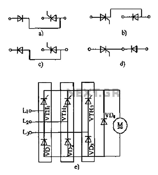
The thyristor linking arm rectifier module is a three-phase half-controlled bridge rectifier circuit. The thyristor-rectifier module linking arm consists of a thyristor and a rectifier diode connected in series or parallel, designed to fulfill specific requirements in power circuits....
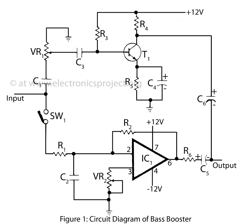
The bass booster featured on this website enhances the beat frequency while maintaining the integrity of the high-frequency response. The circuit diagram for the bass booster, along with various radio circuits, is also provided. The bass booster circuit operates by...