
The Active High Pass Filter

Active high-pass filters are essential components in electronic circuits, designed to allow signals with frequencies higher than a certain cutoff frequency to pass while attenuating signals with lower frequencies. The primary function of these filters is to enhance signal integrity in applications such as audio processing, communications, and instrumentation.
The frequency response of an active high-pass filter is characterized by its cutoff frequency, which is determined by the values of resistors and capacitors used in the circuit. The cutoff frequency (fc) can be calculated using the formula:
fc = 1 / (2πRC)
where R is the resistance and C is the capacitance. Above this frequency, the output signal is significantly amplified, while below it, the signal is increasingly attenuated.
Op-amp voltage gain is a critical aspect of active high-pass filters. The gain can be adjusted by selecting the appropriate feedback and input resistor values in the op-amp circuit configuration. The gain (A) can be expressed as:
A = Vout / Vin = (Rf / Rin) + 1
where Rf is the feedback resistor and Rin is the input resistor. This gain allows for the amplification of the desired high-frequency signals while suppressing unwanted low-frequency noise.
The construction of an active high-pass filter typically involves operational amplifiers (op-amps), resistors, and capacitors. A common configuration is the Sallen-Key topology, which provides a simple and effective means to implement the filter. In this configuration, the op-amp is used in a non-inverting mode, with the resistive and capacitive components determining the filter's characteristics.
When designing an active high-pass filter, it is essential to consider factors such as component tolerances, power supply requirements, and the specific application needs to ensure optimal performance. Proper simulation and testing of the circuit can further validate its functionality and reliability in real-world applications.Electronics Tutorial about Active High Pass Filter including its High Pass Filter Frequency Response, Op-amp Voltage Gain and Active Filter Construction.. 🔗 External reference
Related Circuits
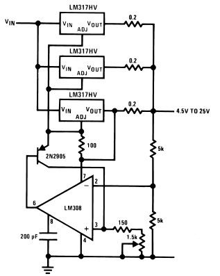
The LM317HV adjustable regulator is capable of supplying over 1.5A across an output voltage range of 1.2V to 57V. The design of this high current power supply is straightforward, as the LM317HV requires only a few external resistors to...
The goal is to transmit additional information through the use of articles. If there are any issues related to article content, copyright, or other concerns, please contact us via email at [email protected] within 15 days. The content will be...
The three-amplifier implementation of the state-variable filter in Figure 1 provides for second-order bandpass, highpass, and lowpass responses. The strength of the circuit, however, is in the bandpass response (VOUT/VIN), in which it's easy to achieve high gain (G)...
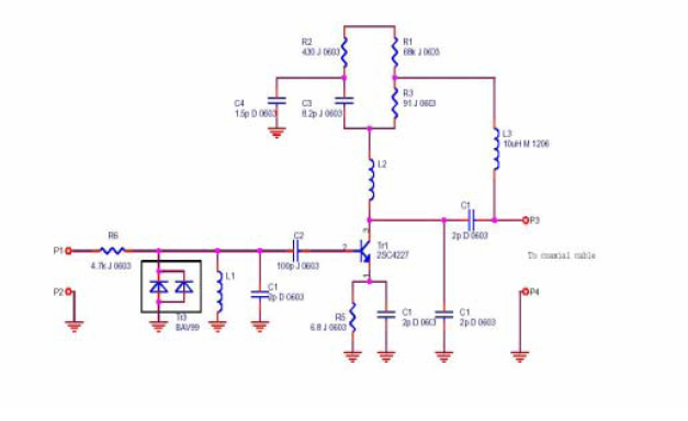
A flat mobile active car antenna is being tested with a Terratec Cinergy DT USB XS Diversity digital tuner. The antenna is designed to enhance signal reception for mobile digital television. The flat mobile active car antenna is engineered to...
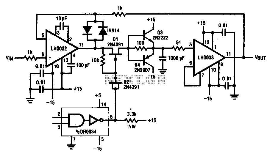
This circuit demonstrates a 10 V acquisition time of 900 ns with 0% accuracy and a droop rate of only 100 µV/ms at an ambient temperature of 25°C. A faster acquisition time can be achieved by using a smaller...
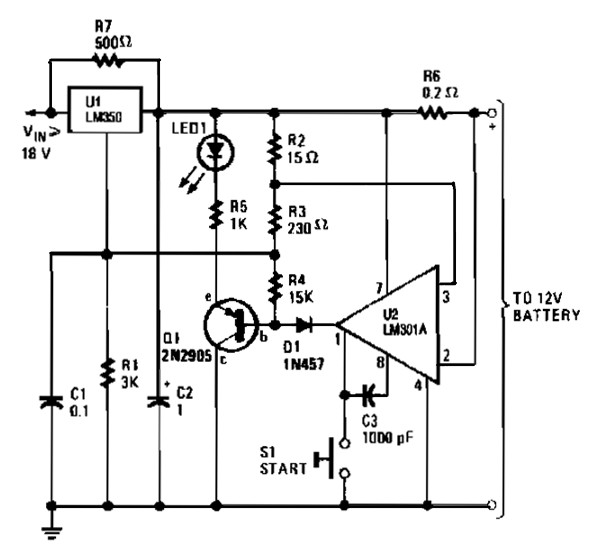
The gelled lead-acid battery charger circuit diagram enables rapid charging of gelled lead-acid batteries and automatically shuts off upon reaching full charge. Initially, the charging current is maintained at 2 A; however, as the battery voltage increases, the current...