
Meter load economizer circuit diagram

The circuit described involves a meter designed to measure electrical parameters through voltage and current coils interfaced with a power line. The configuration ensures that the voltage coil remains energized, permitting continuous operation of the measurement system. This is crucial for accurate readings, as it allows the device to capture fluctuations in voltage without interruption.
When the load (RL) experiences sudden changes, such as a surge or a disconnection, the circuit is designed to respond dynamically. The current flowing through the load can cause the voltage coil to activate rapidly. This feature is essential for maintaining accurate metering under varying load conditions, as it prevents erroneous measurements that could arise from transient conditions.
Moreover, when the load is disconnected, the circuit is designed to cut off the current to the voltage coil, effectively eliminating no-load losses. This characteristic enhances the efficiency of the system by minimizing energy wastage when the load is not present. The design prioritizes both functionality and efficiency, ensuring that the meter operates optimally across a range of load conditions.
Overall, this application circuit exemplifies a robust approach to electrical measurement, integrating responsive features that enhance accuracy while reducing unnecessary power consumption.Application circuit of the device as shown in principle. In the meter, the voltage and current coil and the coil is connected to the power line, whether or not connected to a l oad, voltage coil always steal versed let down Nai Mu Yi G H bound in a league grab S Chi CE module electrical circuit you can Depletion of the table to solve the problem, when the current in the coil circuit load RL string Pops, also the coil voltage is turned on instantly, without affecting the electricity metering; when the load RL is disconnected, the voltage coil current was cut off, so then there is a no-load loss.
Related Circuits
The power supply has been simplified. Power transformers and rectifiers have been omitted, and some components from the MOSFET voltage regulator circuits have been removed, including 1N5242 zener diodes between the source and gate and 10k resistors in series...
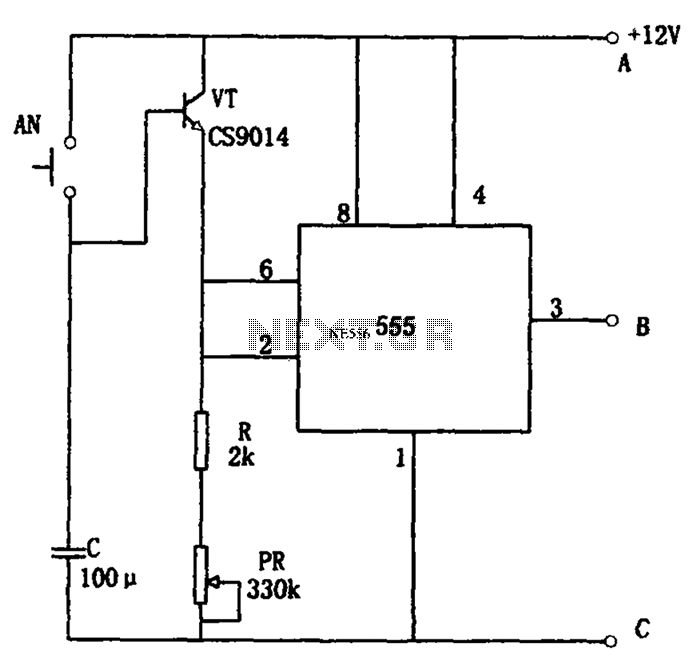
The circuit features a straightforward long timing mechanism. Activating switch AN initiates the timing process, while tone PR allows for timing adjustments. The timing range spans from 3 minutes to 220 minutes. With a capacitance value of 2200 µF,...
A diode, such as the IN4148, has a typical temperature coefficient of -2 mV/°C at a 1 mA diode current. Transistors Q1 and Q2 form a constant current source. Diode D1 serves as the temperature sensor. Integrated circuits ICl-a...
This circuit generates sine wave oscillations, but it can also be modified to produce triangle or square wave functions. The frequency is adjustable by varying the current. By disconnecting the 20k resistor (RIN) from the reference (REF) pin (pin...

This is a light sensor circuit designed to detect darkness, utilizing the op-amp 741 integrated circuit as the primary control element. The circuit is straightforward and specifically designed to sense light during nighttime. The light detection is accomplished using...
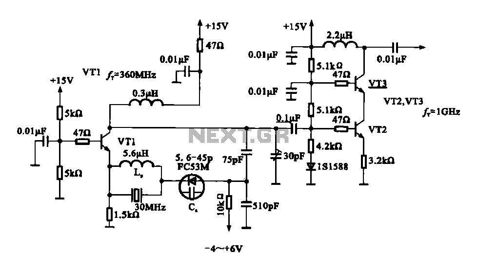
A variable frequency oscillator transistor circuit, primarily functioning as an oscillator, incorporates a crystal resonator and a varactor diode. The output is amplified, typically used for generating high-frequency signals. This 30 MHz transistor circuit features an inductor (LP) connected...