
The Colpitts oscillator

The Colpitts oscillator is a type of LC oscillator that generates sine wave signals at a specific frequency determined by the values of its inductors and capacitors. In this circuit, the crystal SJT acts as a frequency-determining element, ensuring stability and precision in the output frequency of 1499 kHz. The capacitors C2 and C3 form a capacitive voltage divider that influences the feedback voltage fed back to the base of the transistor, which is essential for maintaining oscillation.
The resistors R2 and R3 serve as part of the emitter feedback network. They create a voltage divider that provides a portion of the output signal back to the input, which is crucial for sustaining oscillation. The interaction between the capacitors and the resistors enables fine-tuning of the feedback level, thereby stabilizing the oscillation amplitude.
The output of the Colpitts oscillator is a sine wave signal, which can be accessed at the collector of the transistor. This output can be utilized in various applications, including signal generation, clock pulses for digital circuits, and as a local oscillator in radio frequency (RF) applications. The design parameters, such as the values of the capacitors and resistors, can be adjusted to achieve the desired frequency and output characteristics, making the Colpitts oscillator a versatile choice for frequency generation in electronic circuits.Figure shows the Colpitts oscillator circuit. It has a base frequency crystal, and the frequency is 1499 kHz, crystal SJT is connected to the both ends of capacitor C2, C3. Emitter divider resistor R2, R3 provide basic feedback signal, the feedback voltage is controlled by the capacitive dividers C2, C3.
SJT crystal provides l499kHz sine wave signal for the.. 🔗 External reference
Related Circuits
A voltage-controlled oscillator (VCO) is an electronic signal generator that produces a signal with a variable frequency, which is dependent on an input voltage level. A voltage-controlled oscillator is a fundamental component in various electronic applications, including phase-locked loops (PLLs),...

Q is the transistor, L1 and L2 form a resonant circuit, with L2 also serving as a feedback network. The feedback voltage is transmitted to the transistor base through the coupling capacitor Cb. Figure 2 illustrates the communication channel,...
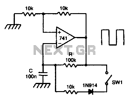
This circuit incorporates a Schmitt trigger and an integrator configured around a single operational amplifier (op-amp). The timing is regulated by an RC network. The voltage at the inverting input tracks the exponential charging of the capacitor within defined...
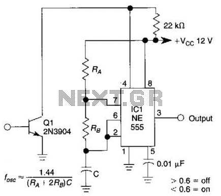
This gated 1-kHz oscillator provides press-to-turn-off functionality, along with waveforms available at the output of pin 3 and across capacitor C1. The gated 1-kHz oscillator circuit is designed to generate a square wave output at a frequency of 1 kHz....
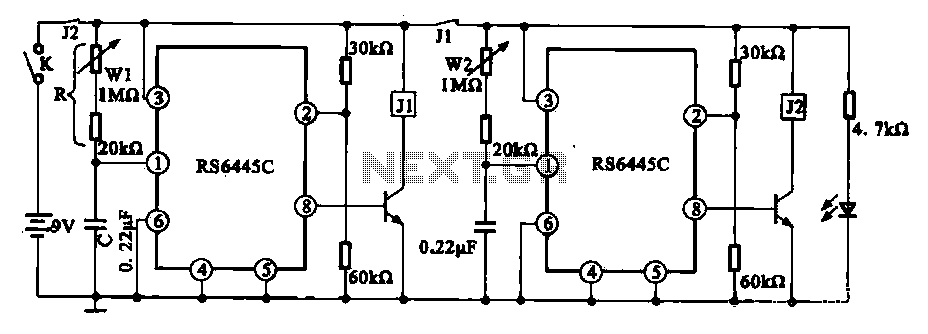
The timing integrated circuit (IC) RS6445C functions as a blocking oscillator. It features two segments, WI and W2, which are utilized to adjust the working time and the closure time. These adjustments can be continuously set within a range...

This is a design circuit for a low distortion crystal oscillator. The circuit generates a sine wave with low phase noise and distortion, allowing for the use of a crystal with less than 1mV dissipated across it. The crystal...