
the dc motor circuit

The basic DC motor circuit allows for a simple on/off control of the motor. By connecting the battery to the motor through the alligator leads, the motor can be activated or deactivated based on the connection of the leads. However, for applications requiring direction control and speed modulation, the H-bridge circuit is essential.
An H-bridge consists of four switches (typically transistors) arranged in a bridge configuration. By controlling the states of these switches, the current flow through the motor can be reversed, allowing for bidirectional control. For instance, turning on switches S1 and S4 while turning off S2 and S3 will cause the motor to rotate in one direction. Conversely, activating S2 and S3 while deactivating S1 and S4 will reverse the motor's direction.
In addition to direction control, the H-bridge can also facilitate speed control through pulse-width modulation (PWM). By varying the duty cycle of the PWM signal applied to the transistors, the average voltage and current supplied to the motor can be adjusted, thereby controlling its speed.
In summary, while a basic DC motor circuit suffices for simple applications, an H-bridge circuit provides the necessary functionality for advanced control of DC motors, enabling both direction and speed modulation essential for mobile robotics.Choosing the right DC motor is critical when building mobile robots. Testing DC motors is an easy process and can be done by building a simple DC motor circuit. All that is required to build this circuit is a DC motor, a battery power source of at least 3 V, and red and black alligator leads. To build the circuit, the red alligator lead is connected to the positive terminal of the battery and motor, whereas the black alligator lead is connected to the negative terminal of the battery and motor.
In order to control the functioning of a DC motor, a specialized DC motor circuit can be used, such as an H-bridge. The H-bridge circuit design is an array of transistors that work along with resistors and diodes to command a DC motor..
🔗 External reference
Related Circuits
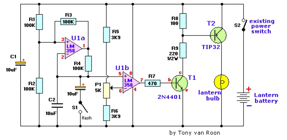
The electronic lantern control circuit enhances an existing battery-powered lantern or flashlight, or can be incorporated into a custom design, by providing high-efficiency dimming and flashing capabilities. This circuit is particularly useful in automotive applications, serving as an effective...
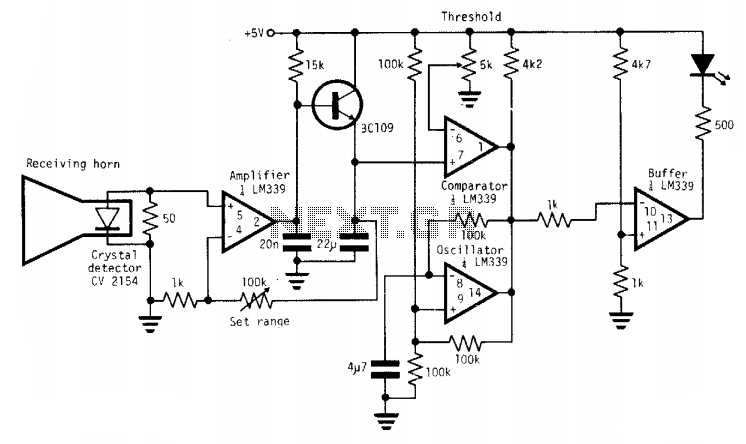
A simple X-band radar detector can indicate changes in RF radiation strength at levels as low as 2 mW/cm². When radiation strikes the detector diode, it generates a voltage at the input of an amplifier. The gain of this...
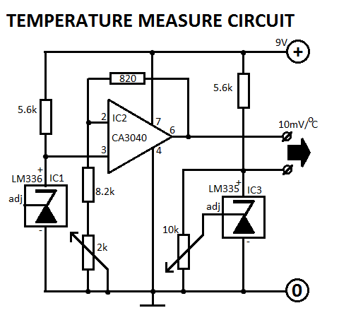
This circuit is designed for Fahrenheit measurements, with the freezing point set at 320°F. At 2120°F, P2 is adjusted to achieve an output voltage of 0.9V. The circuit operates by utilizing a temperature sensor that converts temperature readings into a...
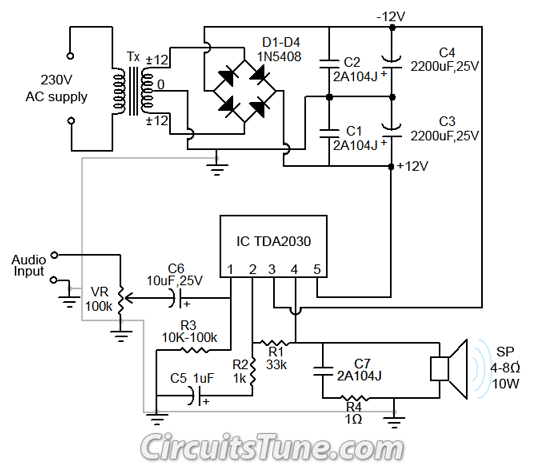
All ground points in the circuit should be connected to a single point and grounded if possible, or connected to the transformer's 0V marked wire as shown in the circuit. In electronic circuit design, proper grounding is crucial for maintaining...
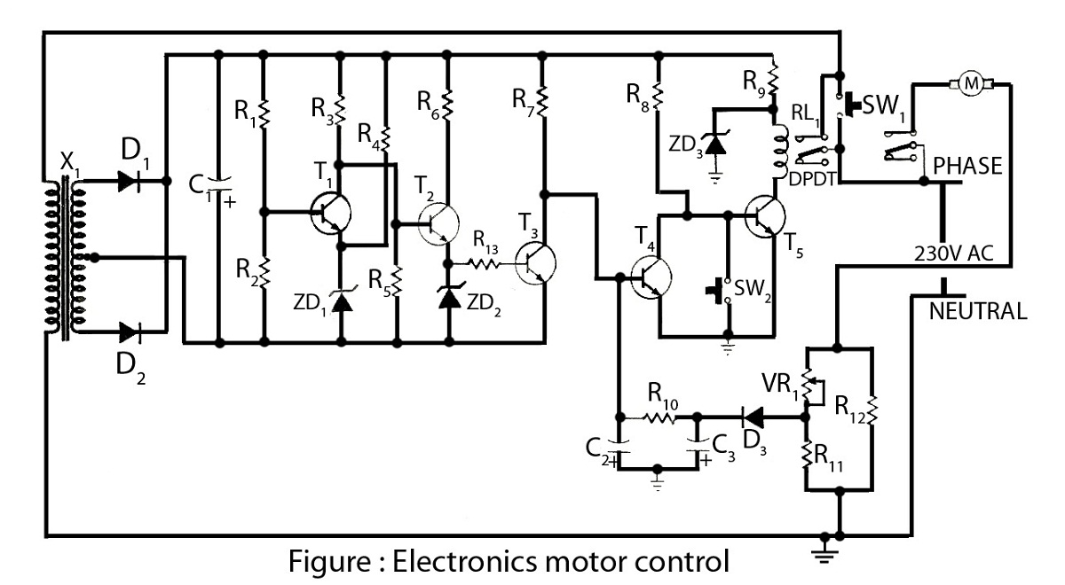
Electronics motor control is a simple circuit made without an integrated circuit (IC). It involves the electronic control of an AC motor and includes a circuit diagram along with a description of the electronics motor controller. The electronics motor control...

The proposed remote control circuit can be utilized to control any electrical device within a range of 100 meters. This concept involves modifying an existing remote bell unit circuit, making the process straightforward. However, the construction aspect necessitates electronic...