
how to make remote control circuit from

The remote control circuit is designed to utilize a radio frequency (RF) communication system, which allows for wireless control of devices over a considerable distance. The core components of this circuit include a transmitter, a receiver, a flip-flop circuit, and a relay. The transmitter sends RF signals when activated, while the receiver picks up these signals and triggers the connected components.
The flip-flop circuit serves as a memory element, maintaining the state of the relay even when the transmitter is turned off. This is crucial for applications where the controlled device needs to remain activated without continuous input from the transmitter. The flip-flop can be built using a popular IC such as the 555 timer configured in bistable mode, which can be easily integrated with the receiver's output.
The relay acts as a switch that can handle the voltage and current requirements of the electrical gadgets being controlled. It is essential to select a relay with appropriate ratings to ensure safe operation. The power supply for the circuit can be derived from a standard transformer, which steps down the mains voltage to a suitable level for the circuit components.
The assembly of the circuit should be done with care, ensuring all connections are secure and properly insulated. The new housing should be designed to provide adequate space for all components, along with ventilation to prevent overheating. Once assembled, the circuit can be tested within the specified range to ensure reliable operation.
In summary, this remote control circuit provides a practical solution for wireless control of electrical devices, leveraging existing technology in a modified form. With careful construction and assembly, it offers an effective means to enhance everyday convenience in home automation.The proposed remote control circuit idea can be used for controlling any electrical gadget within a range of 100 meters. Since the idea here is to modify an existing circuit of a remote bell unit, becomes super easy without any complications.
However the construction part does require the involvement of electronic assemblies so this project ma y not be considered entirely a layman`s project. We all have seen and probably used remote bell gadget in our homes. The device is basically a wireless RF receiver and a transmitter set which can be used for producing alarm sounds remotely for calling or indication proposes. The receiver unit positioned anywhere within this limit instantly plucks the trigger and switches the in built musical bell, sounding the alarm.
The trigger may last for a few moments even after the transmitter is switched OFF. If we are able to mod the receiver part of the unit so that the received trigger can be used to operate a relay instead of the usual alarm, our job is done. However before we indulge into the modification process, it would be necessary to make the Flip Flop circuit first, which would be later on required to be integrated with the receiver set of the remote bell.
The flip flop section is a very simple configuration consisting of just a single IC and a few other passive components. The entire circuit may be buikt over a small general purpose board with the help of the shown schematic.
You will find a small speaker connected via a couple of wires which terminate from the circuit board of the unit. Just cut-of the wires from the speaker, remove the entire circuit from its housing and screw it inside a new housing, which should be relatively bigger in size so that it can accommodate the flip flop section, the transformer power supply section and also the relay assembly.
Your RF remote control circuit is ready and may be used for controlling any electrical gadget that you may prefer, wirelessly, across a radial distance of around 100 meters. 🔗 External reference
Related Circuits
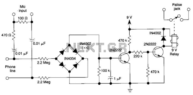
The DC voltage on a telephone line typically ranges from 45 to 50 V when on-hook and drops to around 6 V when off-hook. This circuit utilizes the voltage drop to activate a relay, which in turn controls a...
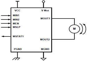
The schematic presented illustrates a 5A H-Bridge Module designed for the operation of a single Bipolar DC motor. The H-Bridge Module includes a header set (J2) and a connector terminal set (J1). Below is the pinout description for the...
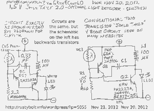
A schematic of a two-transistor Joule Thief was presented in a YouTube video by Sanjev21, which has since been removed. The two-transistor Joule Thief is a compact and efficient circuit designed to extract energy from low-voltage sources, such as depleted...
The use of a quarter-wave parallel-wire line as a tuning unit has been discussed in the chapter on Short-Lines, where it was pointed out that these circuits have comparatively high Q even at higher frequencies. Their significant length (approximately...
This circuit is a 6-zone alarm system designed for independent operation, suitable for small office or home environments. It can be adapted to utilize a combination lock or keypad for setting and resetting the alarm. All zones, Z1 to...

This is a simple automatic light switch circuit designed for bedrooms. After construction, connect the input terminals of this circuit in parallel to the internal buzzer terminals of a quartz alarm clock. When the clock alarm is activated, the...