
SimpleTimer with Musical Alarm

The circuit timer with a musical alarm is designed to provide a user-friendly timing solution with an audible output. The core of the circuit is based on a CMOS oscillator/divider (IC1), which generates a precise timing signal. This component is selected for its low power consumption and efficiency, making it suitable for battery-operated applications.
The adjustable time delay feature is facilitated through the use of a variable resistor (VR1), allowing the user to set the desired timing interval. This flexibility is essential for various applications, such as reminders or alerts. The output signal from IC1, once the timing interval has elapsed, triggers the NPN transistor (T1). This transistor acts as a switch, connecting the melody generator IC (IC2) to the power supply, thereby enabling it to produce sound.
The zener diode (ZD1) plays a critical role in voltage regulation, ensuring that IC2 operates within its specified voltage range of 3.3V. This regulation is vital for the stable performance of the melody generator, preventing potential damage from overvoltage conditions.
The melody generator (IC2) is responsible for producing the desired sound output. The audio signal generated from pin 1 of IC2 is amplified by a driver transistor before being sent to a loudspeaker. This amplification is necessary to ensure that the sound is audible, particularly in environments with background noise. The volume control feature, implemented through preset variable resistor (VR2), allows users to adjust the loudness of the output, providing further customization of the alarm's sound.
The circuit is activated by pressing switch SW1, which supplies power to the entire system. This simple user interface ensures that the timer can be easily started with minimal effort. Overall, the circuit timer with a musical alarm offers an efficient, adjustable, and user-friendly solution for timing applications, combining both visual and auditory alerts.The circuit timer with musical alarm use famous CMOS oscillator/divider IC (IC1 ). Although this circuit operates in 9V its standby current drain is very low. The time delay of timer circuit can be adjusted by adjusting the preset VR1. The base of npn transistor T1 is connected to pin 3 of IC1 through resistor R4 and its emitter terminal is connec ted with pin 2 of melody generator IC (IC2) in order to provide positive supply when adjusted time delay is over. Here the zener diode ZD1 is used as regulator which reduce power supply to required for operation of IC2 i.
e. 3. 3V. Lastly for music output the output from pin 1 of IC2 is fed to loud speaker via driver transistor and its volume is controlled by preset VR2. For starting the timer power is supplied by pressing switch SW1. 🔗 External reference
Related Circuits
This circuit is a simple wire loop alarm that can be used in doorways, hallways, or any other place the tripwire will be broken by intruders. The circuit has a built-in siren, but it can be replaced by a...
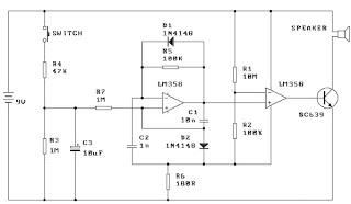
When the switch is pressed, capacitor C3 charges through resistor R4 with a time constant of 0.47 seconds. Upon releasing the switch, C3 discharges more slowly through resistors R7 and R3, with a time constant of approximately 5 seconds....
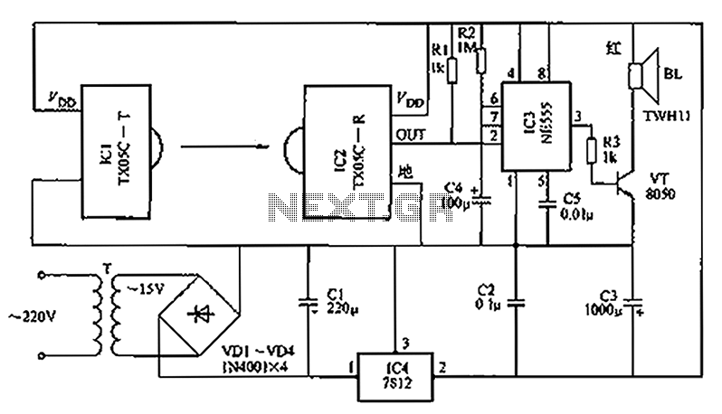
A new type of infrared system utilizes the TX05C radio sensor module for a burglar alarm designed for doors and windows. This system operates in the infrared spectrum, which is invisible to the human eye, making it suitable for...
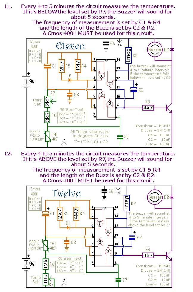
This is a selection of small self-contained alarm circuits. They have a very low standby current; and are suitable for battery operation. The described alarm circuits are compact and designed for low power consumption, making them ideal for battery-powered applications....

This is an enhanced 5 digit keypad which may be used with the Modular Alarm System. The enhanced 5-digit keypad serves as a user interface for the Modular Alarm System, allowing users to input numeric codes for system control. The...
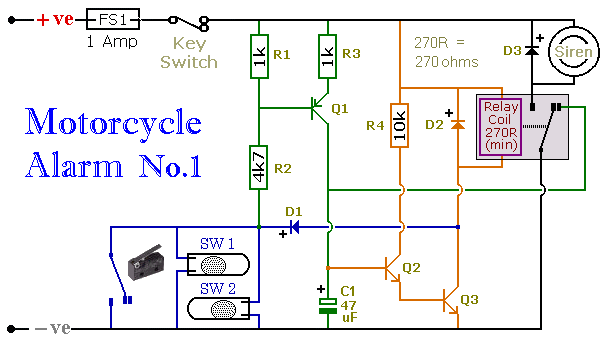
When one of the normally-open switches is closed, two actions occur. First, the negative side of the relay coil connects to ground through D1, energizing the relay, which in turn activates the siren. Second, the emitter-base junction of Q1...