
The Effects of Turning off a Converter with Self-Driven Synchronous Rectifiers

Synchronous rectification is a technique employed in power conversion circuits, particularly in DC-DC converters and power supplies, to improve efficiency by reducing conduction losses. Unlike traditional diode rectification, where diodes are used to convert AC to DC, synchronous rectification utilizes active switching devices, typically MOSFETs, to perform the rectification process. This approach significantly minimizes the forward voltage drop associated with diodes, leading to lower power dissipation and improved thermal performance.
In a synchronous rectifier circuit, the control mechanism is crucial for determining the optimal timing for switching the MOSFETs. This is often achieved through feedback loops that monitor the output voltage and adjust the gate signals of the MOSFETs accordingly. The synchronous rectifier operates in conjunction with a PWM (Pulse Width Modulation) controller, which regulates the duty cycle of the switching devices to maintain the desired output voltage level.
The implementation of synchronous rectification is particularly beneficial in low-voltage applications, where the efficiency gains can result in significant power savings and reduced heat generation. However, it is important to note that synchronous rectification circuits typically require more complex control strategies and may not be suitable for all applications, particularly those requiring load-sharing configurations. In such scenarios, careful design considerations must be made to ensure stability and reliability in the power delivery system.This type of circuit can never be used in a load-share configuration Synchronous rectification is one of the best ways to improve the efficiency of the low-voltage.. 🔗 External reference
Related Circuits
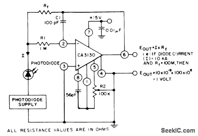
The circuit employs three CA3130 BiMOS operational amplifiers in an application that is sensitive to sub-picoampere input currents. It generates a ground-referenced output voltage that is proportional to the input current flowing through the photodiode. The described circuit utilizes three...
The two circuits demonstrate the process of opening a relay contact shortly after the ignition or light switch is turned off. The capacitor becomes charged, and the relay remains closed until the voltage at the diode anode reaches +12...
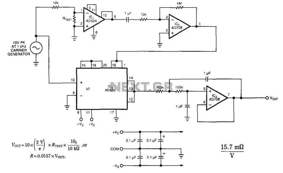
The circuit employs a synchronous detection method to measure low-level resistances. Other low-resistance measuring circuits may introduce excessively large currents into the system under test. This circuit synchronously demodulates the voltage drop across the system under test, allowing the...
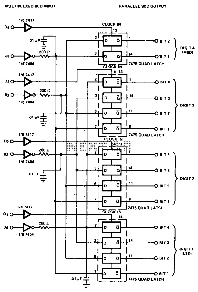
The converter is composed of four quad bistable latches that are activated in the correct sequence by the digit strobe output from the LD110. The complemented outputs (Q) of the quad latch set represent the state of the bit...
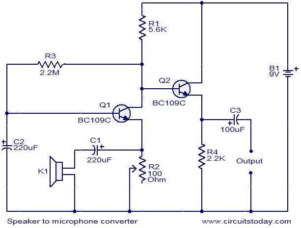
This circuit provides a straightforward method for converting a loudspeaker into a microphone. When sound waves impact the diaphragm of the speaker, fluctuations occur in the coil, generating a small induced voltage that is typically low in magnitude and...
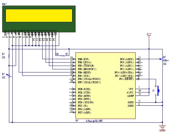
A straightforward tutorial on utilizing the ADC (Analog to Digital Converter) unit of the AVR microcontroller, demonstrated with the Atmega8, including a circuit diagram and code examples. The ADC unit in the Atmega8 microcontroller is a crucial component that allows...